Best Seller
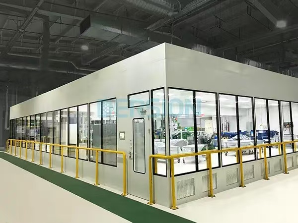
Modular Cleanroom Design — Layouts, FFU & HVAC Best Practices
Introduction to Modular Cleanroom Design
Modular cleanrooms provide flexible, cost-effective solutions for industries requiring controlled environments.
Whether for pharmaceutical manufacturing [citation:2], electronics assembly, or biotechnology R&D, proper design
ensures compliance with ISO 14644 standards [citation:6] and GMP regulations. This comprehensive guide provides
layout examples, FFU placement strategies, HVAC Modular Cleanroom Design principles, and technical specifications to help you design
optimal modular cleanroom facilities. Deiiang™ modular solutions incorporate industry best practices for maximum
efficiency and compliance.

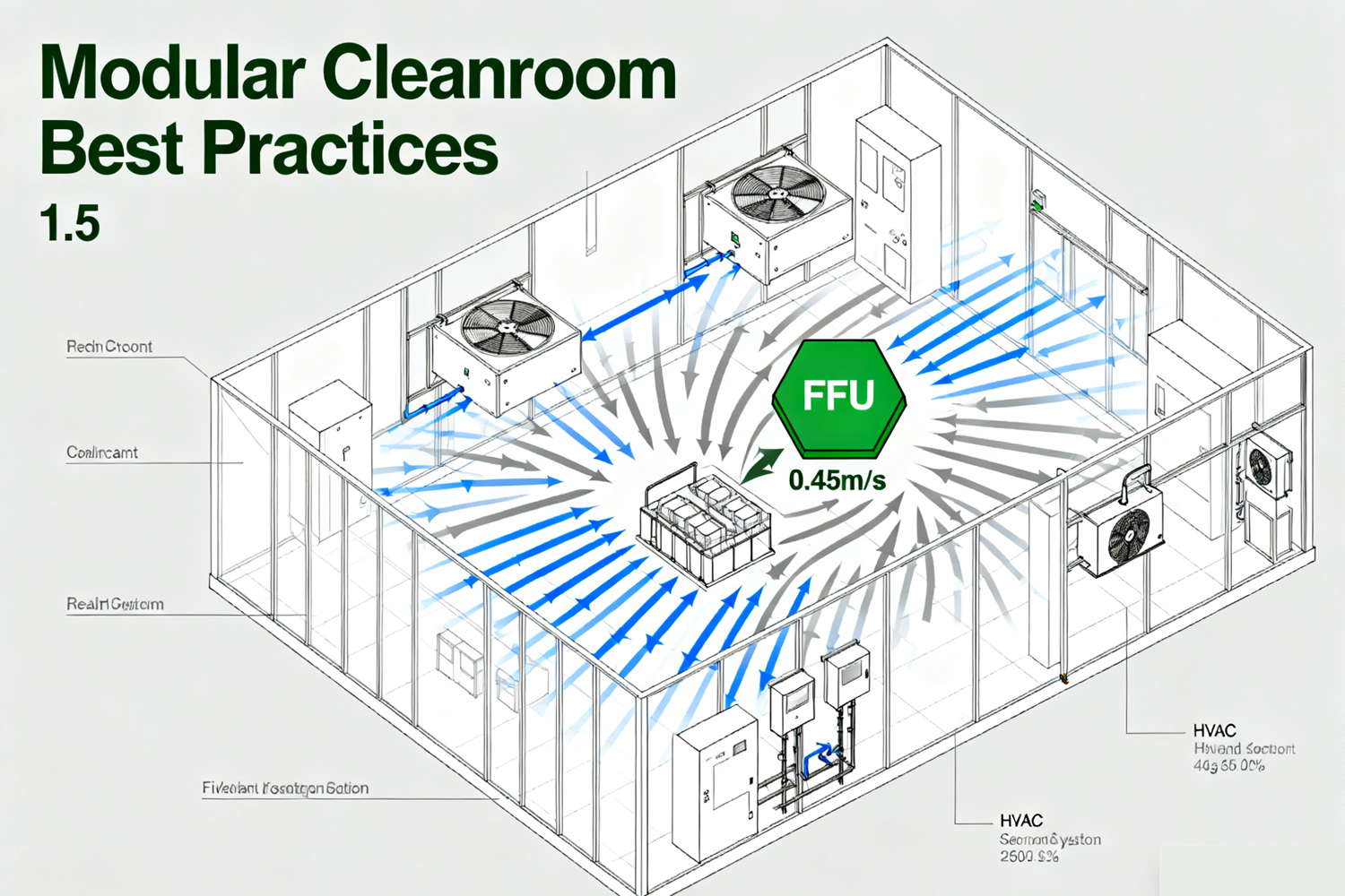
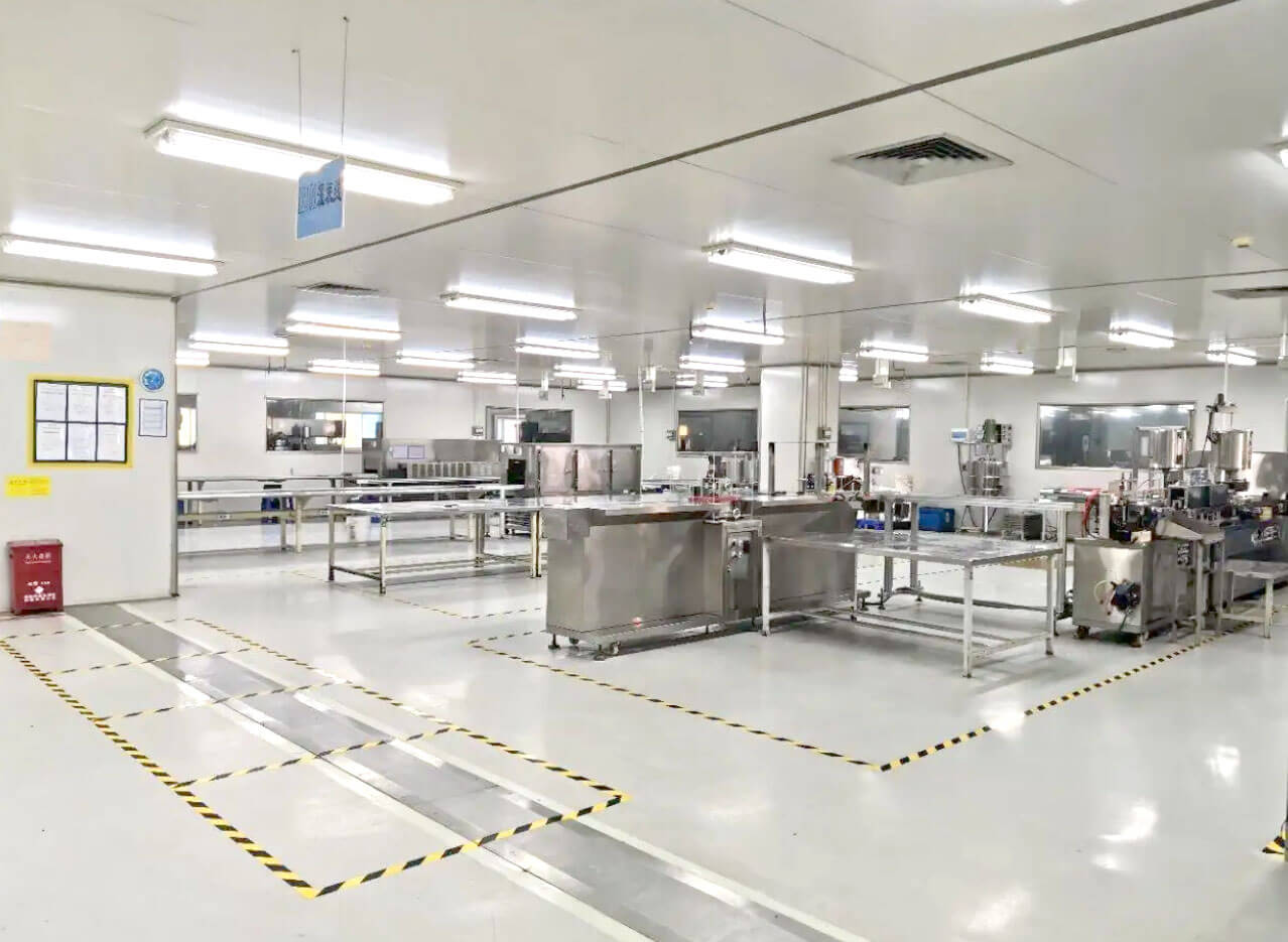
Modular cleanroom design layout diagram
Design Principles & Objectives
Cleanliness Classification
Map ISO 14644-1 classes [citation:6] to specific operational requirements:
- ISO 5 (Class 100): Critical filling operations, sterile products
- ISO 7 (Class 10,000): Primary manufacturing areas
- ISO 8 (Class 100,000): Support areas and gowning rooms
Contamination Control
Implement comprehensive contamination control strategies:
- Personnel and material flow separation
- Positive pressure cascades (15+ Pa between zones)
- Smooth, cleanable surfaces [citation:1]
- Proper gowning procedures [citation:2]
Operational Efficiency
Design for maintainability and scalability:
- Modular components for easy reconfiguration
- Accessible service corridors
- Energy-efficient systems [citation:7]
- Future expansion capabilities
Design Process Overview
Key Validation Stages
Following installation, modular cleanroom design undergo rigorous qualification:
- Installation Qualification (IQ): Verify all components installed correctly
- Operational Qualification (OQ): Confirm systems operate as specified
- Performance Qualification (PQ): Demonstrate consistent performance under load
Deiiang™ provides complete validation documentation packages with all modular cleanroom projects.
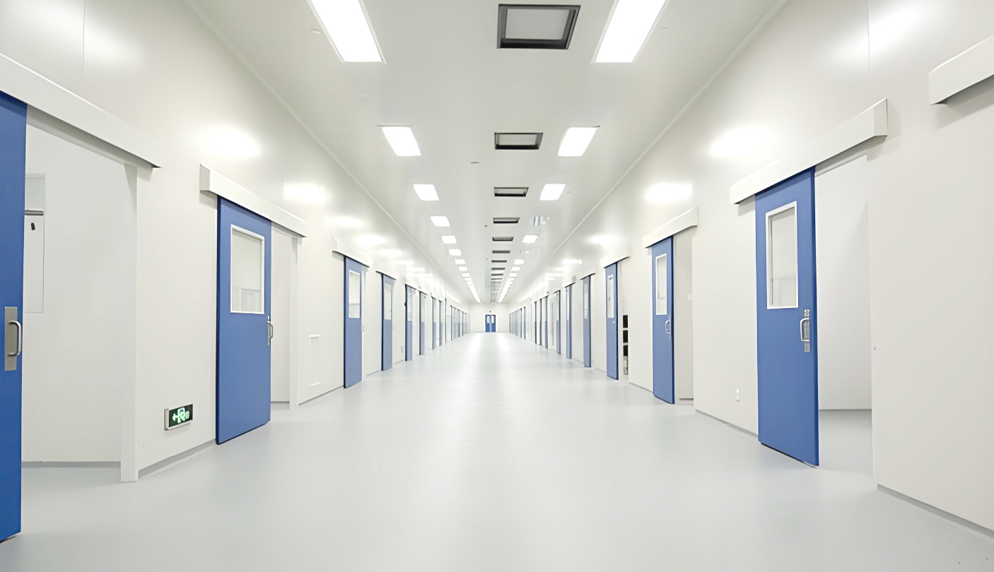
Layout Examples & Floor Plans
Small R&D Lab (20–50 m²)
Compact design for research and development activities:
- Cleanliness: ISO 7 primary area, ISO 8 support
- Key zones: Processing area, gowning room, airlock
- Personnel flow: Single-direction movement
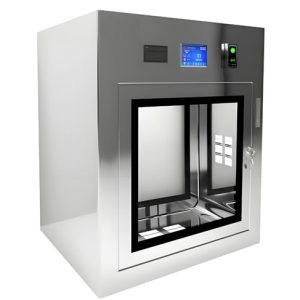
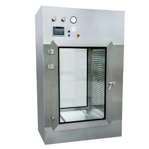
- Material flow: Pass-through chambers
- Minimum corridor width: 1.2 meters
Pilot/SME Production (100–300 m²)
Medium-scale production facility with optimized workflows:
- Cleanliness: ISO 7 primary, ISO 8 secondary
- Key zones: Processing, packaging, QC, changing rooms
- Personnel flow: Separate entry/exit routes
- Material flow: Dedicated material airlocks
- Minimum corridor width: 1.8 meters
High-throughput Production (500m²+)
Large-scale manufacturing with complex zoning:
- Cleanliness: Multiple ISO classes (5, 7, 8)
- Key zones: Multiple processing lines, warehouse, QC labs
- Personnel flow: Multi-stage gowning procedures
- Material flow: Automated material handling systems
- Minimum corridor width: 2.4 meters
FFU Placement & Laminar Flow Design
FFU Calculation Methodology
Air Changes per Hour (ACH) Method:
Where:
- Room Volume = Length × Width × Height (m³)
- ACH = Air Changes per Hour (varies by ISO class)
- FFU Flow Rate = Typical 0.45-0.55 m³/s per FFU
Coverage Percentage Method:
Typical coverage percentages:
- ISO 5: 80-100% coverage
- ISO 7: 25-40% coverage
- ISO 8: 15-25% coverage
Example Calculation: ISO 7 Cleanroom
For a 10m × 8m × 3m ISO 7 cleanroom with 600mm × 1200mm FFUs:
- Room volume: 10 × 8 × 3 = 240 m³
- Recommended ACH for ISO 7: 30-50 [citation:7]
- Using 40 ACH: (240 × 40) / (0.5 × 60) = 32 FFUs
- Coverage method: (80 m² × 0.3) / 0.72 = 33 FFUs
Result: Install 32-34 FFUs for optimal performance
FFU Grid Configuration
ISO 7 Configuration:
- FFU spacing: 1800-2400mm centers
- Perimeter offset: 600-900mm from walls
- Maintenance access: 600mm minimum between units
- Redundancy: 5-10% spare capacity
ISO 5 Configuration:
- FFU spacing: 1200-1800mm centers
- Full ceiling coverage with minimal gaps
- Maintenance access: Integrated walk-on ceilings
- Redundancy: 10-15% spare capacity
FFU Quick Calculator
Recommended FFU Configuration
HVAC & Airflow Design Considerations
System Configurations
Centralized AHU + FFU
Combination of central air handling and localized filtration:
- AHU handles temperature, humidity, and pressurization
- FFUs provide final HEPA filtration and laminar flow
- Ideal for large facilities with multiple zones
- Higher initial cost but better overall control
MAU + RAU + FFU [citation:7]
Modular approach for flexibility and energy efficiency:
- MAU (Make-up Air Unit) handles fresh air treatment
- RAU (Recirculation Air Unit) manages internal air
- FFUs provide terminal HEPA filtration
- Excellent for modular expansion and retrofit projects
Airflow Parameters
| ISO Class | Air Changes per Hour (ACH) | Face Velocity (m/s) | Pressure Differential (Pa) | Return Air Height |
|---|---|---|---|---|
| ISO 5 (Class 100) | 240-600+ | 0.45 ±0.1 | 10-15 | Low side wall |
| ISO 6 (Class 1,000) | 90-150 | – | 10-15 | Low side wall |
| ISO 7 (Class 10,000) | 30-60 | – | 10-15 | Low side wall |
| ISO 8 (Class 100,000) | 15-25 | – | 10-15 | Low side wall |
Deiiang™ HVAC Design Tip
Implement variable frequency drives (VFDs) on FFUs and AHUs to reduce energy consumption by 25-40% while maintaining precise environmental control. Our modular systems include integrated VFD controls as standard.
Electrical & Service Interface Requirements
Power Distribution
- FFU power: 1-1.5 kVA per FFU (220V/1PH or 380V/3PH)
- Lighting circuits: Separate circuits for cleanroom and service areas
- Equipment power: Dedicated circuits for process equipment
- Backup power: Essential systems on UPS or generator
- Emergency lighting: Mandatory per building codes
Lighting Requirements
- General illumination: 500-800 lux at work plane
- Emergency lighting: Minimum 200 lux
- Fixtures: Sealed LED fixtures with smooth surfaces
- Color temperature: 4000K recommended for visual clarity
- Control: Zoned switching with occupancy sensors
Grounding & ESD Protection
Essential for electronics and pharmaceutical applications:
- Equipment grounding: Separate ground bus for sensitive equipment
- ESD protection: Conductive flooring and work surfaces
- Static dissipative: 10^6-10^9 ohms resistance
- Personnel grounding: Wrist straps and footwear testing
Cable Management with Item Wall Ducts [citation:1]
Item’s wall duct systems provide safe cable routing within cleanroom walls. The 20mm gap allows direct cable placement without additional processing. Outlets, switches, and network connections can be clipped directly between wall duct profiles.
Ceiling Height & Plenum Requirements
| Application | Minimum Clear Height | Recommended Height | Plenum Depth | Critical Factors |
|---|---|---|---|---|
| R&D Laboratories | 2.7m | 2.8-3.0m | 0.8-1.2m | Equipment access, serviceability |
| Pharmaceutical Production | 2.8m | 3.0-3.2m | 1.0-1.5m | Filling lines, large equipment |
| Electronics Manufacturing | 2.8m | 3.0-3.5m | 1.2-1.8m | Tool installation, maintenance access |
| Medical Device Assembly | 2.7m | 2.8-3.0m | 0.8-1.2m | Modular workstations, flexibility |
| Biotechnology | 2.8m | 3.0-3.3m | 1.0-1.5m | Fermenters, piping systems |
Structural Considerations
Ceiling structure must support FFUs, lighting, and service loads:
- FFU weight: 40-60 kg per unit
- Walk-on ceilings: Minimum 2 kN/m² capacity [citation:1]
- Service access: Integrated access panels and catwalks
- Vibration control: Isolated mounting for sensitive equipment
Plenum Design
Proper plenum design ensures optimal airflow and maintenance access:
- Sealed construction: Prevents contamination migration
- Adequate depth: Allows proper airflow distribution
- Service clearance: Minimum 600mm for maintenance access
- Lighting integration: Recessed fixtures for clean sightlines