+86 13638632902
 Jason@cleanroomequips.com

 MENU
MENU
The fan filter unit (ffu) layout directly affects airflow uniformity, efficiency in controlling particles, and overall cleanliness stability in large clean rooms. Poor ffu spacing and layout lead to the formation of low-movement zones, short air-circuits, and irregular airflow, which jeopardize compliance with good manufacturing practices and iso classifications. This work analyzes how to select the optimal FFU location and successfully distribute air and avoid polluting from the standpoint of design standards, field tests, and CFD simulations.
Why FFU Layout Defines Real-World Cleanroom Performance
Whether a cleanroom design is good or bad does not depend on the number of FFUs, but on whether these devices can form a stable, uniform, and verifiable airflow pattern.
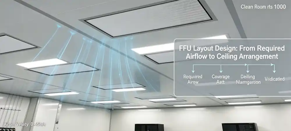
The installation location, spacing, ceiling coverage, air supply direction, installation height, and return air grille location of the FFU, all of these will directly affect the final airflow distribution effect. For large cleanrooms of iso 5 to iso 8 standards, the layout of FFUs directly affects product quality and compliance acceptance results.
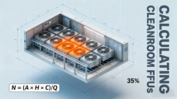
Typical FFU ceiling layout for a large-scale cleanroom facility
Executive Summary
Key Takeaways:
- The number of FFUs we need to configure cannot be determined solely by the cleanroom area, and also necessary to take into account factors such as cleanliness level, target wind speed, ceiling coverage, equipment layout, and return air path.
- The spacing between FFUs should also be planned reasonably. Excessive spacing can easily lead to areas with insufficient wind speed and dead zones in the airflow; although denser spacing results in stronger airflow, it also increases upfront equipment costs, day-to-day energy use, and ongoing maintenance demands.
- For large cleanrooms, we recommend that you perform CFD airflow simulation and iso 14644-3 smoke visualization test. This allows for early verification of airflow uniformity and the identification of blind spots within the environment.
- Deiiang™ provides one-stop support from FFU selection, layout simulation, on-site installation to final verification, and based on the cleanroom dimensions, equipment locations, and actual process requirements, a more suitable FFU layout scheme will be developed.
What Is FFU Layout Design, and Why It Matters for Air Uniformity
FFUs Are More Than “Ceiling-Mounted Filter Fans”
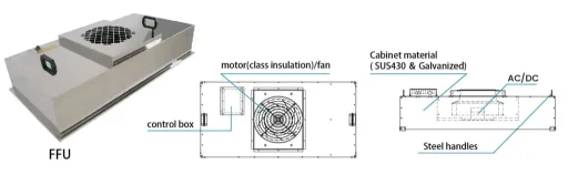
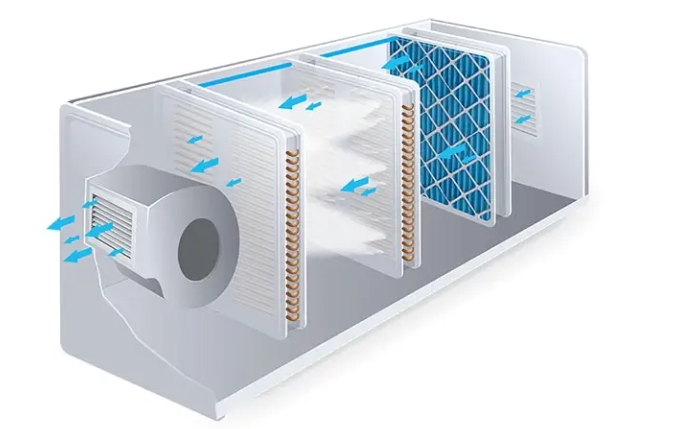
The fan filter unit integrates a fan, a high-efficiency filter, a housing, and a control system. It is responsible for supplying filtered air to the cleanroom. The airflow then follows a precisely designed return air path, carrying away the particulate matter in the air.
In large facilities, simply increasing the number of FFUs without thinking often fails to solve the actual problem. Walls, production equipment, workbenches, lighting fixtures, ceiling structures, and return air grilles can all alter the original direction of airflow.
Link Between Airflow Uniformity and Cleanliness
Uniform airflow does not mean that the wind speed must be exactly the same at every location in a cleanroom. Rather, it refers to maintaining a stable airflow speed, direction, and coverage area within key regions, there should be no obvious low-wind-speed areas, airflow swirling areas, or "dead zones" where particles can easily accumulate.
In high-standard clean areas, for example, aseptic production operation areas, semiconductor wafer fabs, and precision assembly areas. The airflow must not only be clean, must also flow along predictable and controllable paths. This is to prevent particulate matter from lingering, flowing back, or spreading in critical process areas.
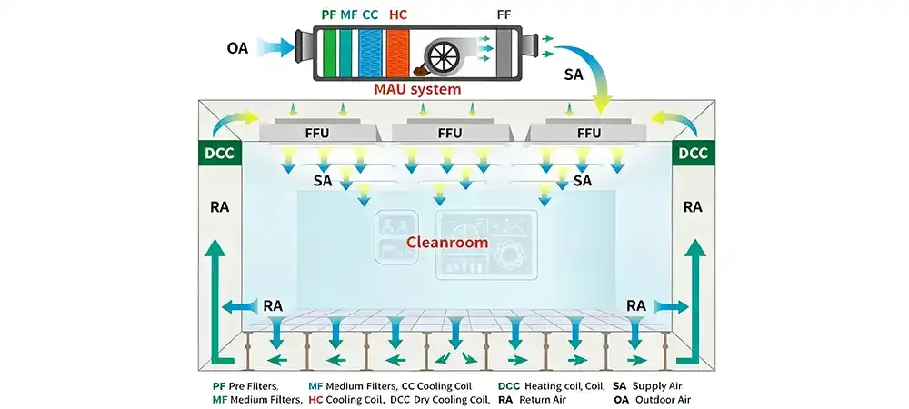
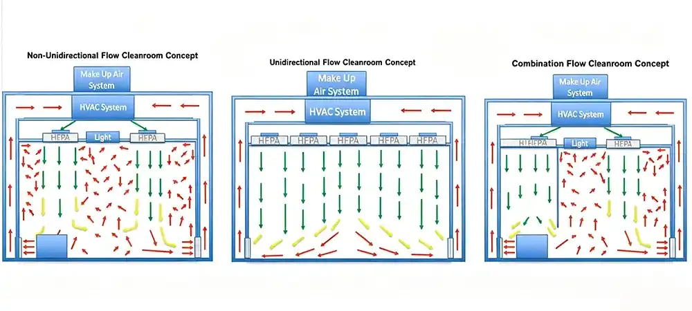
FFU, HEPA filter, supply airflow, and return air path principle
Five Key Factors to Evaluate Before FFU Layout Design
1. Target Cleanliness Class
Different cleanliness classes impose different requirements for room design.
iso 5 zones demand more stringent controls for airflow direction, coverage, and removal of airborne contamination. ISO 7 and iso 8 zones may operate with less Fan Filter Unit (FFU) coverage, and concentration controls may be ACHieved with adequate air changes and return air design.
One project's ceiling coverage may not be applicable to another project. Similar-sized cleanrooms may have very different FFU counts requirement due to process equipment, density, and number of personnel.
2. Room Area and Ceiling Height
The floor area determines the FFU coverage design. Ceiling height affects the airflow stability and velocity decay by the time the air reaches the distal work plane.
In tall rooms, insufficient FFU velocity, inadequate return paths, and large equipment obstructions may result in cycles and turbulence of the airflow prior to reaching the work surfaces. For large cleanrooms, the use of Computational Fluid Dynamics (CFD) prior to installation is strongly recommended.
3. Process Equipment and Obstructions
Large equipment, partitions, racks, robotic arms, conveyors, and even standing personnel act as obstructions to the air.
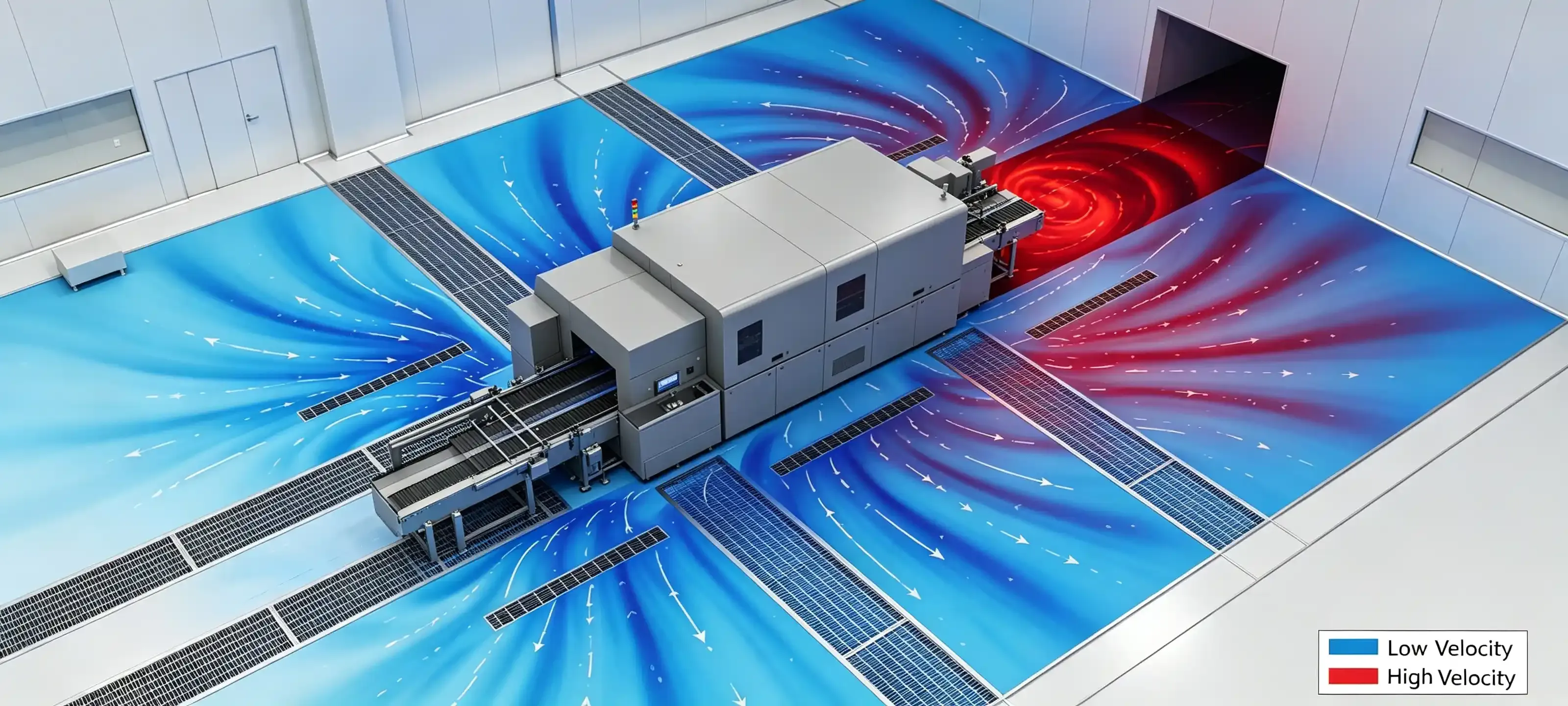
A common problem is that FFUs appear to be evenly distributed throughout the ceiling, but zones of lower airflow are present on and behind equipment. These surfaces also become contaminated and release airborne particles when personnel move or doors are opened.
4. Return Grille Position and Air Return Path
FFU supply is only half of the design; the other half is air return.
If supply and return are too close, clean air exits the critical zone and short circuits. If supply is too far, stagnant air pockets exist in the zone.
Field Practice Note: Airflow is balanced through the alignment of return air grilles with FFUs and blank panels. Uniform sizing of blank panels along with the correct sizing of return air columns should create a uniform pressure in the FFU layout and eliminate the potential for air leakage across the panels.
5. FFU Performance Consistency
In a cleanroom, all FFUs should deliver the same levels of airflow, static pressure, and filtration performance. An uneven cleanroom airflow problem can occur with mixing even the best design layout with different FFU models or filter grades.
Deiiang™ FFUs deliver tight performance consistency, verified by factory testing:
- Rated airflow range: 500–2,500 m³/h per unit (size-dependent)
- External static pressure capability: up to 120 Pa
- Operating noise: 50–65 dB(A) at 1 m distance
- Motor power consumption: 80–220 W
- Filter grade: H13 / H14 HEPA, U15 / U16 ULPA
- Speed control: EC motor with 0–100% stepless regulation
- Factory airflow consistency: ±5% tolerance across production batch
According to Deiiang group control systems, surrounding FFUs can increase their airflow to maintain minimum coverage, and support N+1 redundancy. This occurs when one unit fails or when a filter is clogged, thus achieving N redundancy and eliminating the need for manual control.
Designed by Jason Peng, each unit is calibrated to maintain stable airflow as filter loading increases over service life.
CFD analysis of airflow shadow zones caused by process equipment
FFU Spacing: How to Determine the Right Distance
⚠️ Engineering Pitfall: The "Perfect Grid" Illusion
Some new designers design layouts that distribute roof FFUs in evenly spaced grid patterns. In large clean rooms this is not suitable. This is mostly due to bulk laden process equipment that create flow shadows. The best design layouts are often asymmetrical, with FFUs being placed directly above critical process bulk flow with lower density placed in less critical flow spaces, such as corridors.
Avoid Fixed Spacing Rules
What is a typical FFU spacing? This is one of the most frequently asked questions, but there is no standard spacing to apply to clean rooms.
FFU spacing is determined by unit size, unit airflow ratings, target airflow face velocity, ceiling effective coverage, room and equipment heights, airflow return strategy, room cleanness and target risk.
Production critical areas will need reduced airflow coverage. Less coverage can be found in support areas, hallways, and gowning areas.
Basic Calculation Framework
The following equations are an initial spacing guide. Designs in the absence of site specific guidance and engineering review should not be considered final.
Total required supply airflow:
Total Airflow (m³/h) = Cleanroom Area (m²) × Target Average Velocity (m/s) × 3600
Number of FFUs required:
Number of FFUs = Total Required Airflow / Actual Airflow per FFU
Design margins and anticipated equipment engagement state and duty cycle should be factored in for loss and maintenance cycles.
For unidirectional flow systems and local priority zones, the total airflow for the task should still be considered, but supply coverage and airflow at the working plane should be prioritized.
Ceiling Coverage as a Preliminary Metric
Design systems using the ceiling coverage ratio of the effective supply area of FFUs to the total ceiling area. This is a rough design metric but should be validated by CFD or site assessments.
Different applications require coverage of varying degrees. Certain local critical zones may require additional coverage, while background zones can rely on some degree of cost-effectiveness.
Standard FFU Ceiling Coverage Ratios by ISO Class
While CFD analysis can help to determine precise coverage, the industry provides various standards for coverage that help calculate baseline ceiling coverage percentages:
| Cleanliness Level | Typical Airflow Pattern | Recommended FFU Ceiling Coverage |
|---|---|---|
| ISO Class 1 to 4 | 100% Unidirectional (Laminar) | 100% |
| iso class 5 (class 100) | Unidirectional | 60% – 90% (depending on process risk) |
| ISO Class 6 (Class 1,000) | Mixed / High-rate Turbulent | 25% – 40% |
| iso class 7 (Class 10,000) | Turbulent Flow | 15% – 25% |
| iso class 8 (class 100,000) | Turbulent Flow | 5% – 15% |
ISO 1–4
- Pattern: 100% unidirectional
- Coverage: 100%
ISO 5 (Class 100)
- Pattern: unidirectional
- Coverage: 60% – 90%
ISO 6 (Class 1,000)
- Pattern: mixed / high-rate turbulent
- Coverage: 25% – 40%
ISO 7 (Class 10,000)
- Pattern: turbulent flow
- Coverage: 15% – 25%
ISO 8 (class 100,000)
- Pattern: turbulent flow
- Coverage: 5% – 15%
🧮 Quick FFU Quantity Estimator
Input your cleanroom dimensions and target ISO class to get a baseline estimate of required standard 1170×570 mm FFUs.
Estimated Baseline Requirement:
0 Units
*Assumes standard FFU footprint of approx. 0.66 m² (1170×570mm). This is a preliminary estimate for budget purposes. Actual quantities require CFD validation.
| Application Zone | Common Airflow Strategy | FFU Layout Focus | CFD Simulation |
|---|---|---|---|
| Aseptic filling core | Partial or full unidirectional flow | High coverage, stable downflow, low turbulence | Strongly recommended |
| Semiconductor process bay | Full-area downflow | Supply continuity over equipment, side low-level return | Strongly recommended |
| Medical device assembly | Mixed flow or local boost | Airflow around workstations and equipment | Recommended |
| Electronics assembly | Non-unidirectional or mixed flow | Avoid dead zones from heat sources and equipment | Recommended |
| Gowning rooms, corridors | Dilution ventilation | air changes, pressure differential, return path | Case-dependent |
Aseptic Filling Core
- Strategy: partial/full unidirectional flow
- Focus: high coverage, stable downflow
- CFD: strongly recommended
Semiconductor Process Bay
- Strategy: full-area downflow
- Focus: supply continuity over equipment
- CFD: strongly recommended
Medical / Electronics Assembly
- Strategy: mixed flow or local boost
- Focus: avoid equipment dead zones
- CFD: recommended
Gowning / Corridors
- Strategy: dilution ventilation
- Focus: air changes & pressure
- CFD: case-dependent
Cleanroom Dead Zones: How They Form and How to Fix Them
What Is a Dead Zone?
Dead zones don't equate to no airflow, instead, it means that the velocity is far below the design limits, or the air continuously recirculates, and thus the particulate matter is unable to be removed.
Zones in smoke studies demonstrate long smoke retention, upward rollback, lateral spread, and smoke pooling behind equipment.
Four Most Common Dead Zone Types
- Behind or on top of large process equipment
- Ceiling perimeter areas with insufficient FFU coverage
- Zones where supply and return air short-circuit
- Areas with frequent disturbance from heat sources, personnel, or door openings
How to Reduce or Eliminate Dead Zones
Dead zones cannot be solved by simply adding more FFUs. The more effective method is to figure out what the issue is, and then make changes accordingly.
If the cause is obstruction, then move the FFUs, provide localized supply in the critical areas, or change the return path around the pieces of equipment. If the cause is short circuiting, the FFU’s return grilles may need to be repositioned and the supply-return pressure balance may need to be adjusted.
CFD velocity contour showing dead zone formation behind large equipment
Airflow Uniformity: How to Verify Real-World Performance
Average Velocity Can Hide Local Problems
For many projects, the average velocity is often used to analyze performance, but averages can hide a lot of problems.
As a demonstration of this, an area may achieve the average target, but may have a large number of under and over velocity points that in turn lead to issues of unstable contamination control in critical processing zones. Testing should include the distribution of points, the maximum and minimum flow rates, the range of deviation, and the direction of flow.
Three-Tier Verification Approach
- Design-stage validation — CFD simulation predicts FFU discharge, equipment shadowing, return paths, and personnel-related risks.
- Post-installation velocity testing — anemometer measurements at defined grid points evaluate velocity distribution and uniformity.
- Dynamic smoke visualization — ISO 14644-3 compliant flow visualization observes real airflow trajectories under operating conditions, with equipment running and personnel moving.
Deiiang Verification Capabilities
- FFU factory airflow performance testing
- HEPA / ULPA filter integrity leak testing
- On-site cleanroom velocity grid testing
- Pressure, temperature, humidity, and airborne particle testing
- iso 14644-3 airflow visualization smoke studies
- CFD simulation reporting
- Commissioning, tuning, and acceptance support
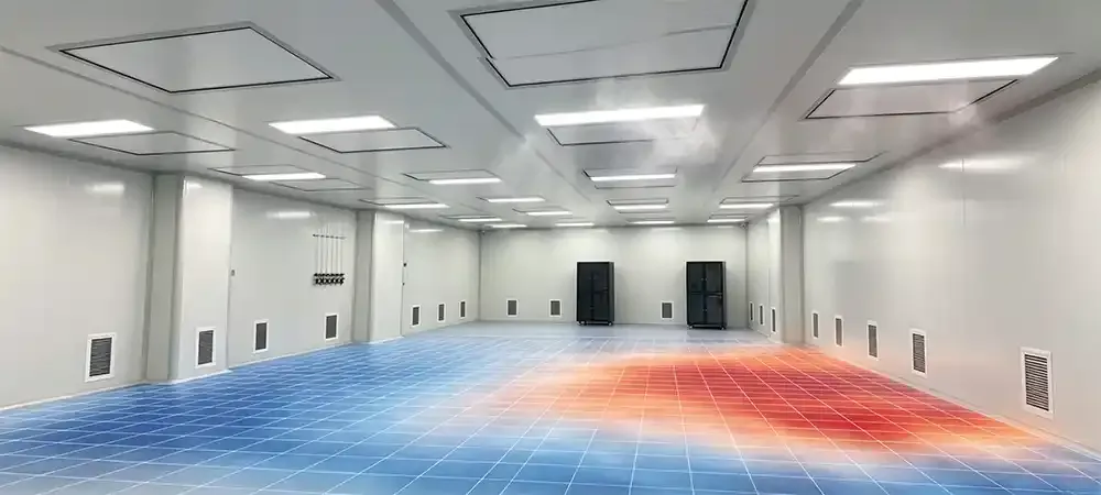
Velocity uniformity heat map from on-site grid measurement
Case Study: Large Electronics Manufacturing cleanroom ffu Optimization
Project Background
One of the world’s largest manufacturers of electronics made an upgrade to its clean production facilities that included precision components assembly and inspection. They included a cleanroom of 1,800 m², RF Class 7, with automation equipment, workstations, and material transfer areas.
The initial layout had FFU coverage that was continuous, provisioned supply of airflow toward equipment, and vague local paths for equipment return. If a conventional grid layout was utilized, it would have negatively impacted the uniformity of the critical airflow.
Project Challenges
- Large floor area with long airflow travel paths
- Tall automated equipment creating rear low-velocity zones
- Tighter particle control in critical operation areas
- Need to balance cleanliness performance with long-term energy cost
- Tight schedule requiring minimal on-site rework
Deiiang Solution
To analyze FFU layout, the Deiiang team gathered data on room dimensions, the structure of ceilings, equipment models, workstation locations, heat sources, and return grilles.
High-density FFU layouts with zonal control were implemented in critical process areas. This allowed the non-critical areas to have their FFU layouts adjusted based on the actual production. FFU placements were moved, based on CFD analysis, away from obstructed areas, and air return patterns were optimized.
Standard Deiiang™ 1170×570 mm FFUs equipped with H14 HEPA filters and EC stepless speed control were used. After FFUs were installed, the team carried out velocity testing, airflow assessment, and particle count.
| Verification Item | Design Target | As-Built Result | Verification Method |
|---|---|---|---|
| Cleanroom area | 1,800 m² | 1,800 m² | As-built drawing / site survey |
| FFU installed quantity | 320 units | 312 units | Equipment schedule |
| Critical zone average velocity | 0.35 m/s | 0.36 m/s | Velocity grid test report |
| Velocity uniformity | ±25% | ±18% | Grid measurement / heat map |
| Particle concentration class | ISO 7 | ISO 7 (mid-zone ISO 6) | Third-party particle count |
| Dead zone improvement | Major reduction | 92% reduction in low-velocity area | CFD + smoke study |
| Unit power consumption | ≤150 W | 138 W average | Factory performance data |
Area & Quantity
- Cleanroom: 1,800 m²
- FFU installed: 312 units
- Method: as-built drawing
Airflow Performance
- Critical zone velocity: 0.36 m/s
- Uniformity: ±18%
- Method: velocity grid test
Cleanliness Result
- Target: ISO 7
- Result: ISO 7 (mid-zone ISO 6)
- Method: third-party particle count
Dead Zone & Energy
- 92% reduction in low-velocity area
- 138 W average unit power
- Method: CFD + smoke study
* Compared with traditional AC motor FFUs, Deiiang EC motor units save approximately 120,000 kWh per year in this 1,800 m² facility.
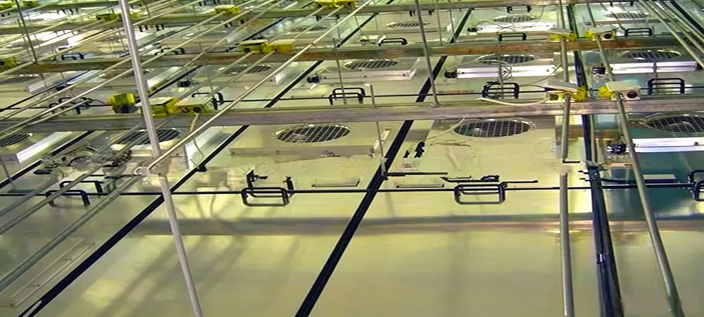
Cleanroom prior to FFU layout optimization
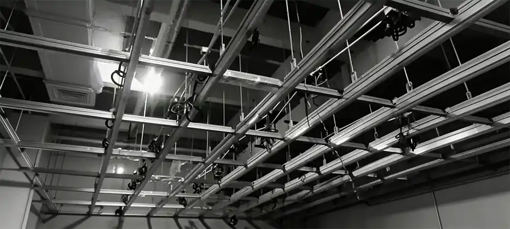
Deiiang FFU installation on site
FFU Layout Optimization Process: From Design to Validation
- Project requirements confirmation
- Cleanliness class and process risk assessment
- Room, equipment, and return air data collection
- Preliminary FFU model and quantity selection
- FFU spacing and ceiling coverage design
- CFD airflow simulation
- Layout adjustment and energy evaluation
- On-site installation and zonal control commissioning
- Velocity, pressure, and particle testing
- ISO 14644-3 airflow visualization validation
- Project handover and maintenance plan
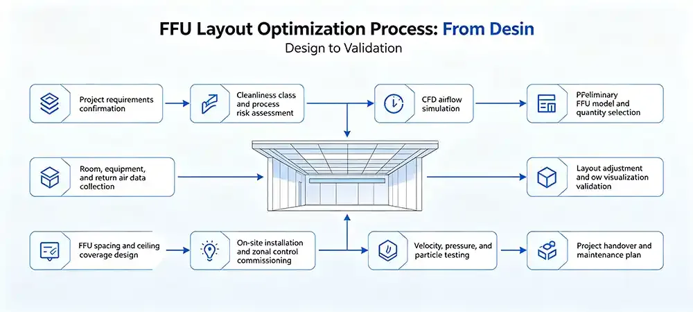
End-to-end FFU layout design and validation workflow
Common Mistakes in Large cleanroom ffu Design
- Mistake 1: Using spatial averaging to determine the number of FFUs. Spatial averaging is a distribution starting point, particularly in the absence of a process risk assessment. Supply design is needed for the critical equipment and high density of personnel and contamination areas.
- Mistake 2: Ignoring airflow impact of equipment and lighting. The airflow is impacted by substructures of equipment, light fixtures, and even cable trays. If these are not included in the CFD models, dead zones are likely to appear during commissioning.
- Mistake 3: Placing emphasis on air supply. If the return paths are not currently managed, air supplied will not effectively remove contaminants. To eliminate stagnation and short-circuiting, the air return paths need to be controlled.
- Mistake 4: Conducting tests in a static, empty room. Tests done in an empty room do not define the working production environment. The environment in which personnel move and equipment operates, and paths are created by the opening and closing of doors and transfer of materials, greatly affect airflow.
How to Select the Right Deiiang FFU System
When FFUs are used, do not compare FFUs based solely on cost and the airflow they are rated at. Compare how the FFUs integrate with the rest of the system and the airflow strategy.
In large cleanrooms, the long-term operating costs are determined by the stability of the per-unit cost of airflow, the efficiency of the filters, the static pressure and energy costs, as well as noise, control integration, and the availability of service.
Deiiang™ provides Full Fan Filter Unit (FFU) range product selection, FFU layout with analysis, CFD, and offers site placement, commissioning, and validation services.
Next Steps:
- Request an FFU layout review
- Get a cleanroom airflow assessment
- Talk to a Deiiang cleanroom engineer
- Download FFU technical specifications
Conclusion: Better Airflow, Not Just More FFUs
In large cleanrooms, uniform airflow is achieved from FFUs, filters, FFU layout, placement and design of equipment, airflow supply and return paths, and airflow verification. This is achieved from the integration of supply units rather than the placement of additional units.
An optimal FFU layout design ensures that clean air is delivered to Critical Process Areas (CPAs) and that airflow takes the shortest and most stable paths. This design also incorporates the balance of the energy and maintenance costs, as well as the costs associated with future production layout changes.
For stringent class 100 cleanroom requirements and/or complex equipment layouts, the integration of CFD prior to construction combined with velocity measurements and iso 14644-3 smoke testing is recommended to assess the layout post construction.
Micro-Glossary
FFU (Fan Filter Unit)
A cleanroom supply device combining a fan and a high-efficiency filter that provides continuous airflow of filtered air to clean, controlled spaces.
Airflow Uniformity
The degree to which the velocity and/or direction of airflow are the same at all points.
Cleanroom Dead Zone
Areas that are slow, stagnant, and recirculating, where particles remain unremoved. Cleanroom dead zones are often found behind large equipment and at the edges of a cleanroom.
CFD (Computational Fluid Dynamics)
A construction prior to flow analysis technology that can predict airflow obstruction, short circuiting, and low velocity zones.
Ceiling Coverage Ratio
An early estimate of supply coverage determined from the total area of the cleanroom ceiling and the effective supply area (via FFU).
ISO 14644-3 Airflow Visualization
The use of smoke for airflow verification will identify areas of recirculation, turbulence, and dead zones as well as the potential for contaminant migration.
Frequently Asked Questions
How far apart should FFUs be placed in a cleanroom?
Several factors will define the best FFU placement, including the target cleanliness class, ceiling coverage, FFU airflow capacity, room height, furniture and equipment layout, and design of the return airspace. Fixed spacing should not be used to replace a customized airflow design.
How do you prevent dead zones in a cleanroom?
The placement of FFUs should not be obstructed by furniture or cleanroom equipment. Consideration should be given to the design of air return pathways. Validation of the design should be done using CFD analysis and smoke test visualizations.
Why is airflow uniformity important in a cleanroom?
Avoiding airflow recirculation zones is critical to maintaining a cleanroom. This is accomplished by ensuring uniform airflow which provides the cleanest air to a work zone.
Is CFD necessary for FFU layout design?
Before FFUs can be located in a large cleanroom, CFD may be necessary for FFU placement with a complex layout, high-risk activities, or within the critical zone of ISO 5.
How can FFU airflow performance be verified after installation?
Common methods of verification include airflow velocity assessment, airflow visualization, smoke studies, particle counters, pressure differential tests, and filter integrity tests.
References
- iso 14644-3:2019 — Cleanrooms and associated controlled environments — Part 3: Test methods
- iso 14644-2:2015 — Cleanrooms and associated controlled environments — Part 2: Monitoring to provide evidence of cleanroom performance