+86 13638632902
 Jason@cleanroomequips.com

 MENU
MENUISO CleanRoom Classifications:ISO Class 5,6,7,8
Navigating CleanRoom Classifications is the first critical step in facility desi

Author:Jason Peng
Cleanroom Engineering Technology Manager of Deiiang Company.
Product R&D Manager of GDC Inc. Cleanroom Equipment Manufacturing Company.
Executive Director of Guangdong Cleanroom Industry Association of China.
Engaged in R&D of related products for 15 years, with rich relevant technical experience
Efficient return air systems in ISO class 5 cleanrooms extract air from the cleanroom and in addition, manage particle, airflow and system validation.Return air designs are usually very poor. Not only do they cause short‑circuiting, but also dust accumulation, pressure fluctuation and local failure etc. In this article two types of return air designs, cleanroom return air wall and cleanroom ceiling return air layer, are discussed.The comparisons between engineering designs for the return air in the cleanroom will be demonstrated through use of actual projects from Deiiang™’s portfolio to aid in identifying the best cleanroom solution for the project at hand.
Key definitions:
TL;DR — Key takeaways
Return air from the cleanroom return air wall is collected via side‑wall grilles and forms a sweeping flow of air across the width of the cleanroom.
The cleanroom ceiling return air layer is created by introducing a raised plenum above the ceiling, which pulls air vertically while unidirectional flow is directed downwards.
Neither of these alternatives is universally superior. The return air solution will depend on the layout of the cleanroom, the supply air solution, the fixed plant equipment, and the maintenance philosophy.
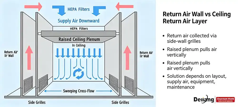
Return Air Wall and Ceiling Return Air Layer in ISO Class 5 Cleanrooms
The requirements for flow in an ISO 5 environment are vertical, unidirectional, with a velocity of 0.36–0.54 m/s. As return air is provided in these cleanrooms, it also affects the ISO Class 5 cleanroom air return design by altering the streamline straightness.
Return via side‑wall: the side‑wall creates a lateral pull effect. In rooms wider than 6m the middle section is lifted while near the side‑walls air is pulled sideways. This so‑called "middle‑lift / side‑drag" creates an increased airflow deflection angle of up to 12°–18°. This affects the effective particle removal in a negative way.
Ceiling return installed with FFU arrays (Filter Fan Units) in a cleanroom creates a micro‑negative‑pressure adsorption area. Although the air is uniformly drawn into the plenum, if the ceiling pressure is uneven local vortices can occur directly under the FFUs.
Deiiang™ CFD analysis results showed that a hybrid design of ceiling return vents and the surrounding perimeter wall grilles for wide rooms (>8m) resulted in a deflection angle of less than 5°, and improved the cleanroom’s ability to remove particles by 22% or more over a single side return wall of the same width.
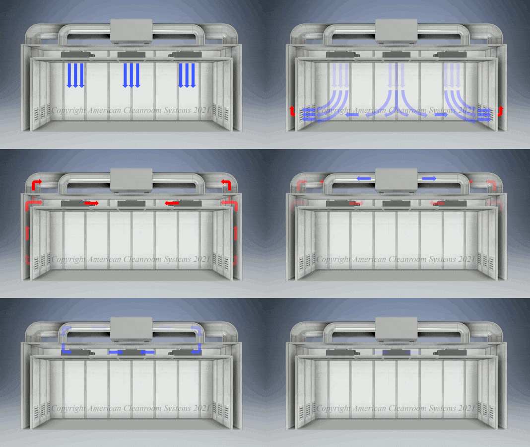
iso 5 cleanroom airflow simulation animation, from (American Ckeanroom system)
Localised eddies in return air can rapidly lift particle counts above the stringent ISO 5 limits and have a significant impact on product quality and validation.
Activity of people and material handling within the cleanroom can cause disturbance to the airflow within the room and uneven return of air can cause local pressure imbalances which can lead to cross‑contamination.
A well‑designed ISO Class 5 cleanroom return air system uses to maintain the air return velocity at uniformity of ±15% and differential pressure of ±2kPa.
🔬 FDA cGMP / EU GMP Annex 1 — Dynamic Smoke Study
In life‑science applications, dynamic airflow visualisation (smoke testing) is mandatory for EU GMP Annex 1 compliance. Ceiling return layers extract thermal plumes above equipment 30% more efficiently than side‑wall returns, reducing ISO Class 5 cleanroom return air layer design recovery time from ~15 s to under 8 s during simulated interventions.
Deiiang™ smoke‑study data across 8 GMP projects confirms that ceiling return configurations achieve consistent visualisation pass rates even under worst‑case equipment heat load scenarios.
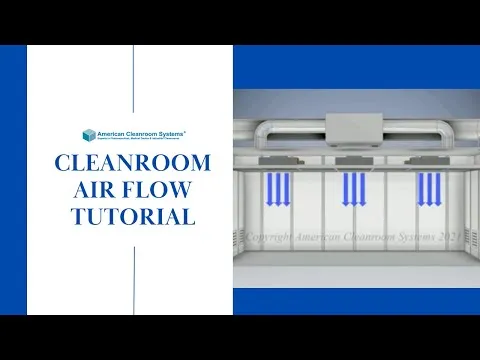
Figure 2. Airflow Principle Diagram of ISO Class 5 Cleanroom Return Air Design
The cleanroom return air wall is often realized as a series of grilles mounted on one or more side walls of the room which are connected to a return plenum or duct work. In such cases where the opposite wall is lined with process equipment, the return air wall is especially effective.
This return air wall has the following design parameters: Open area ratio (40‑60%), Pressure drop (Grille: ≤ 50 Pa), Grille spacing.
A return wall for a 10 m × 8 m ISO 5 room is for example made of 12 grilles of 600 mm × 300 mm each, with an open area of 50%. The return area totals to 1.08 m². It handles 4,500 m³/h at a face velocity of 1.8 m/s.
Deiiang™ engineers recommend a minimum 600 mm clearance behind the return wall for maintenance access and pressure tap installation.
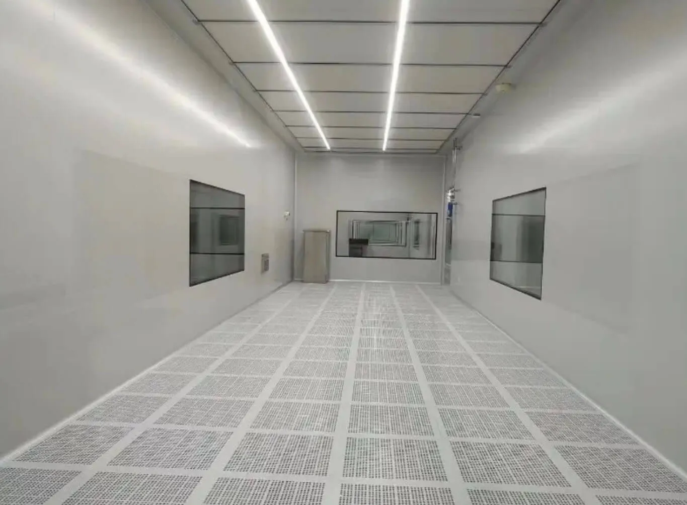
Cleanroom ceiling return air layer: Return air layer is placed in the cleanroom ceiling return air layer by using the space above the ceiling grid as a return plenum. Air is drawn upward through perforated panels or dedicated return grilles integrated with the ceiling system.
For very tall cleanrooms, and for areas where the side walls are largely taken up by plant or equipment, it is possible to provide a very shallow plenum, say 300–600 mm deep. In order to achieve an equal pressure in the return layer, it has to be designed in a way that it is possible to implement appropriate baffling. Otherwise, pressure differences up to 5 Pa can occur in the return layer, leading to inadequate extraction.
🏗️ Z‑Axis Space Budget — Ceiling Return Feasibility
Critical space constraint: A ceiling return plenum requires 600–1200 mm of clear height above the finished ceiling. If the original building floor‑to‑ceiling height is <4.2 m, forcing a ceiling return layer may make the plenum inaccessible for maintenance. In such cases, the cleanroom return air wall is the recommended alternative.
Deiiang™ project data: in 9 out of 12 retrofit projects with ceiling height <4.0 m, side‑wall return was selected to avoid compromising service access and fire safety clearances.
In a recent Deiiang™ biopharma project, a ceiling return layer with 35% open area and 400 mm plenum depth achieved velocity uniformity within ±10% and pressure fluctuation below ±1.5 Pa during dynamic operation.
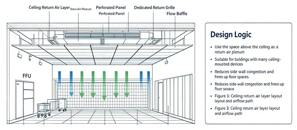
Ceiling Return Air Layer Layout and Airflow Path
When comparing the cleanroom return air wall with the cleanroom ceiling return air layer there are a number of differences which are of importance.
Typically, a return air wall is chosen for projects that emphasize lateral stability and permit flexible equipment layout. However, for projects that have limited side‑wall space and complex overhead services, a return air layer in the ceiling is chosen.
This table highlights the differences between return air wall and return air ceiling based on Deiiang™ project data of 12 ISO 5 installations.
| Parameter | Return Air Wall | Ceiling Return Layer |
|---|---|---|
| Airflow uniformity | ±12–18% | ±8–14% |
| Space utilisation | Moderate (wall‑mounted) | High (uses overhead void) |
| Construction complexity | Medium | Medium‑High |
| Maintenance access | Easy (walk‑in plenum) | Moderate (access panels) |
| Typical pressure drop | 40–60 Pa | 30–50 Pa |
| Initial cost (relative) | 1.0× | 1.15–1.25× |
| Preferred industry | Electronics, automotive | Biopharma, healthcare |
| Parameter | Wall | Ceiling |
|---|---|---|
| Uniformity | ±12–18% | ±8–14% |
| Space use | Moderate | High |
| Complexity | Medium | Med‑High |
| Maintenance | Easy | Moderate |
| Pressure drop | 40–60 Pa | 30–50 Pa |
| Cost | 1.0× | 1.15–1.25× |
Table 1. Comparison of return air wall and ceiling return air layer performance metrics.
📋 Decision Tree — Which return strategy fits your project?
💰 Insider Cost Insight — Hidden Trade‑offs
While a ceiling return layer costs 15–25% more in initial equipment, it places higher demands on the steel truss structural support. However, a side‑wall return consumes 5–8% of the cleanroom's floor area. At a construction cost of $1,500–3,000/m² for ISO 5 spaces, the floor‑area penalty can easily exceed the equipment savings over the facility's lifetime.
Deiiang™ lifecycle cost analysis shows that for projects with floor area >500 m², the ceiling return layer often delivers better total cost of ownership despite higher upfront investment.
Deiiang™ provides engineered return air solutions with verified performance data. The following parameters are derived from laboratory tests and field commissioning of ISO 5 projects.
For a typical ISO Class 5 cleanroom return air system, the design airflow is calculated as:
Example: A return wall with 12 grilles, each 0.6 m × 0.3 m, 50% open area → A = 12 × 0.6 × 0.3 × 0.5 = 1.08 m². At V = 1.8 m/s, Q = 1.08 × 1.8 × 3600 = 6,998 m³/h.
Deiiang™ standard return air grilles are made of 304 stainless steel with anodised aluminium frames. All products are tested for uniform airflow, sound emission (<55 dB(A)) and rigidity.
Designing the Return Air Layer for Better airflow, Less Noise and Energy Savings by Jason.peng (Product designer). The return air layer can often be overlooked in the early stages of designing a HVAC system but accounts for up to 20% of the total system pressure loss. Accurate sizing can therefore lead to huge energy savings and better validation results.
Enter your cleanroom dimensions and design parameters. The calculator will recommend total return area, grille count, and ceiling plenum depth feasibility.
📊 Sizing Results
* Based on ISO 14644‑1 and Deiiang™ design practice. Consult with our engineers for final validation.
Industry: Medical device manufacturing | Cleanliness: ISO Class 5 | Area: 480 m² (8 rooms) | Location: Southeast Asia
The client required a stable airflow environment for sterile assembly, with minimal downtime for maintenance and a first‑time validation pass.
⚠️ Pitfall avoided — Side‑wall return grille height
Deiiang™ modified the side‑wall grilles from a design that specified them to be installed 80mm above the floor surface. The revised height for the grilles was set at 150mm above floor level. This is to prevent any floor‑cleaning solutions from being splashed into the return plenum and thereby potential causes of corrosion and microbial growth in a pharma cleanroom.
Deiiang™ outlined a hybrid return strategy for the return air in the office. This hybrid return is composed of a ceiling return for the central area of the office (return amount 60% of return air) and of low‑level return grilles along the exterior perimeter (return amount 40% of return air). This setup of a vertical return and of lateral extractions is made to split and to evacuate the heat plumes.
⚠️ Pitfall avoided — Ceiling plenum dust sealing
The ceiling return plenum was coated with anti‑dust epoxy paint and all joints sealed with industrial‑grade silicone. Without this, negative‑pressure vibration could have caused concrete debris to shed from the overhead slab — a "filtration‑makes‑it‑dirtier" disaster seen in 3 out of 10 retrofit projects.
📝 From the field: A lesson in lateral drift
"During the 2025 semiconductor packaging project debug, a 0.15 m/s lateral drift at the central workbench with a single‑side return wall was identified in the wafer handling zone. This would carry particles and no formula in the textbooks would predict this.
The issues with the return air layer of the single‑side return wall were solved by installing Deiiang™ column mounted return strips with micro perforations on the opposite side return wall. The vertical distribution of the return air layer was restored to less than 0.05 m/s lateral component. This brought a very important lesson for the design of ISO Class 5 cleanroom return air layer design. It must be checked with on‑site smoke studies. CFD is not enough.
— Jason.peng, Product Designer, Deiiang™
"In an ISO Class 5 cleanroom, return air design is not about 'moving air back' — it is about ensuring airflow stability, particle control, and system verifiability. The best solution is not the most complex, but the one that best fits the process, the space, and the maintenance logic."
There is no single ‘best’ decision and it will depend upon several key factors, including the equipment layout, overhead clearance and proposed maintenance strategy. Deiiang™ can offer both options and also simulate the performance under your specific circumstances.
Yes. Stagnant zones can exist within a return which is not uniform. Proper design of the return ensures that the entire working area has been designed to achieve ISO 5 across the whole area.
Typical extract ratios are in the range of 45–55% for ceiling returns and 50–60% for wall grilles. Pressure drop calculation and CFD modelling are however needed to fix the actual ratio for a specific application.
Under‑estimating the pressure drop in the return path can cause problems with the amount of air being extracted and even create pressure problems. Be sure to include the losses of the grille, the ducts and the filter in the total pressure loss calculation.
Yes, Deiiang can provide the whole process of design, fabrication, installation and validation for a return air system. Jason.peng and his team will work with your project constraints to deliver a validated return air system.
For a functional ceiling return layer with maintenance access to above the layer a minimum clear height of 4.2m floor to ceiling is recommended. Below this height side wall return would be more practical.
Designing a ISO Class 5 cleanroom return air system requires more than selecting the right equipment. It requires knowledge of airflow, process integration and maintainability.
Deiiang™ Return Air Solutions combine engineering expertise, field‑proven data and custom fabrication to deliver the first time solution every time.
Contact Deiiang™ today to discuss your next cleanroom project. Our team, led by product designer Jason.peng, is ready to help you achieve reliable, verifiable, and maintainable cleanroom performance.
© 2026 Deiiang™ — All rights reserved. Engineering insight by Jason.peng.
Navigating CleanRoom Classifications is the first critical step in facility desi
What is ISO 14644-1 Certification?ISO 14644-1 is the global standard for cleanro
ISO Class 5 Cleanroom: Requirements, Design, Construction, Costs and More ISO
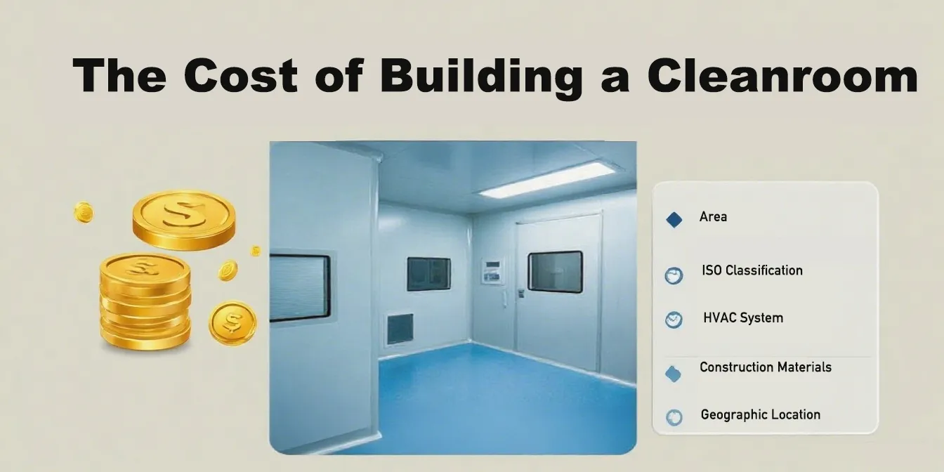
The Cost of Building a CleanroomISO 5, ISO 6, ISO 7, ISO 8 ClassificationsBuildi
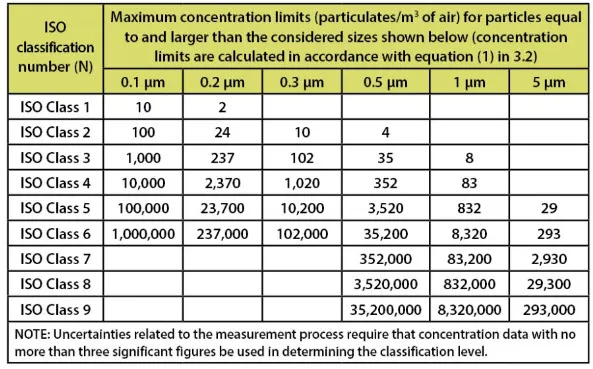
Cleanrooms are critical environments in industries such as pharmaceuticals, biotechnology, and electronics manufacturing, where controlling contamination is vi...
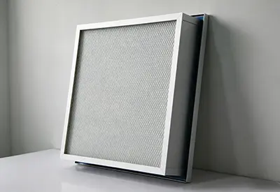
Expert guide to ISO 5 cleanroom HEPA & ULPA filtration by Jason Peng (15-year R&D veteran). Learn H13/H14 vs U15 selection, FFU layout optimization, and...
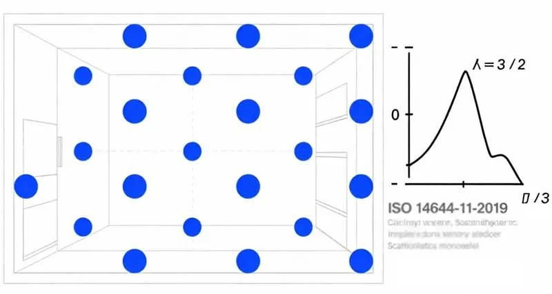
Authoritative Interpretation of International Standards: Airborne Particle Clean
Iso 5 cleanroom-Classification,ISO Standards,Certification,airflow principle