+86 13638632902
 Jason@cleanroomequips.com

 MENU
MENU
Introduction: Airflow as the Circulatory System of Cleanrooms
Cleanroom airflow patterns directly determine whether a facility can consistently meet its target cleanliness class.
Class 5 through Class 8 environments rely on intentional air movement to remove particles and prevent contamination buildup.
ISO 14644 standards serve as the globally recognized benchmark for both design methodology and on-site performance verification.
Executive Summary
- Unidirectional flow serves ISO 5 and cleaner zones via piston-effect particle removal. Deiiang lab data shows up to 85% higher efficiency than turbulent designs under matched conditions.
- Turbulent flow fits ISO 6–8 environments with lower cost, but requires Deiiang CFD simulation to eliminate dead-zone contamination risks.
- iso 14644-3 smoke visualization is the definitive verification method, and a mandatory acceptance metric for all Deiiang turnkey projects.
Unidirectional (Laminar) Flow Deep Dive
Precision laminar flow design delivers uniform, parallel air movement across the entire controlled workspace.
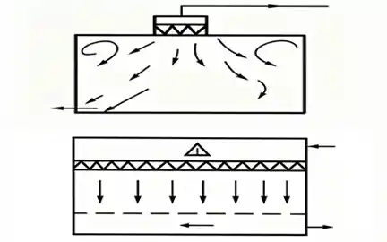
It operates on the piston effect: air moves as a single plug, pushing contaminants straight toward return or exhaust grilles.
Primary applications include aseptic pharmaceutical filling lines and semiconductor wafer fabrication zones.
- Nominal supply velocity: 0.45 m/s at the filter face
- Velocity uniformity: ±20% across the working plane
- Typical cleanliness rating: ISO 5 or higher
Deiiang™ HEPA and ULPA filter modules are engineered for low, stable resistance across service life. The media maintains consistent airflow even as particle loading increases over months of operation.
⚠️ Engineering Pitfall: The Thermal Plume Effect
Never design a unidirectional airflow system without accounting for equipment heat loads. Heat-generating equipment (like ovens or injection molders) creates upward convective currents called thermal plumes. If the downward velocity of the laminar flow (typically 0.45 m/s) is weaker than the upward thermal plume, the airflow will break down, creating a highly contaminated eddy directly over your critical process. Always use CFD modeling for high-heat applications.

Unidirectional flow principle and airflow velocity uniformity heatmap
Turbulent (Non-Unidirectional) Flow Deep Dive
Turbulent airflow controls contamination through dilution and gradual mixing of supply air with room air.
Ceiling diffusers deliver filtered air, which mixes throughout the space to lower overall particle concentration.
This approach offers greater layout flexibility and lower capital and operating costs than unidirectional systems.
Advantages
- Lower initial construction and installation cost
- Flexible layout for equipment and workstations
- Suitable for support and lower-grade clean zones
Limitations
- Eddy zones can trap particles near critical surfaces
- Slower particle removal and longer recovery time
- Not recommended for ISO 5 or aseptic core zones

Turbulent flow dilution and air mixing principle
Deiiang Case Study: Pharmaceutical Aseptic Zone Retrofit
Project Background
A large pharmaceutical manufacturer upgraded its existing filling line from mixed-flow to localized unidirectional flow.
The goal was to achieve sustained ISO 5 conditions at the critical filling point of the production line.
Project Challenges
- Limited ceiling height restricted standard FFU installation depth
- High cleanliness performance was required at reduced supply velocity
- Retrofit had to be completed within a narrow shutdown window
Deiiang Solution
Custom low-profile Deiiang FFU arrays were deployed with optimized outlet spacing over the critical zone.
CFD simulation was used to refine diffuser placement and return air grille positions before installation.
Based on Deiiang field measurement data, the localized contamination recovery time (from ISO 7 contaminated state back to ISO 5 criteria) was reduced from 120 seconds to 28 seconds.

Original cleanroom layout before retrofit

Deiiang airflow control equipment installation

ISO 14644-3 smoke test on-site verification

Final particle count test report and certification
The Cost-Effective Alternative: Mixed Airflow
In many modern cleanroom designs, strict adherence to purely unidirectional or purely turbulent flow across an entire room is unnecessary and costly.
Mixed Airflow combines both strategies: employing local unidirectional flow (via localized FFU canopies or laminar flow hoods) directly over critical operational zones (ISO 5), while maintaining the background room at a lower cleanliness level (ISO 7 or 8) using turbulent dilution.
- Benefit: Drastically reduces total FFU quantity and overall HVAC energy consumption.
- Challenge: Requires precise return-air placement to prevent turbulent background air from being pulled into the critical unidirectional zone.
- Common Use Case: iso 7 cleanrooms with localized ISO 5 process stations, packaging lines, and testing laboratories.
Decision Matrix: How to Choose the Right Pattern
Selecting the correct airflow strategy depends on cleanliness requirements, process risk and available budget.
| Characteristic | Unidirectional Flow | Turbulent Flow |
|---|---|---|
| Typical Cleanliness Class | ISO 5 or cleaner | ISO 6 through iso 8 |
| Key Sizing Metric | Filter Face Velocity (0.3–0.5 m/s) | air changes Per Hour (20–160 ACH) |
| Particle Removal Speed | Very fast (piston displacement) | Slower (dilution mixing) |
| Initial Capital Cost | High | Low to medium |
| Primary Applications | Critical process points, aseptic operations | Corridors, buffer zones, gowning rooms |
Unidirectional Flow
- ISO 5 or cleaner cleanliness rating
- Key metric: filter face velocity 0.3–0.5 m/s
- Very fast piston-effect particle removal
- Higher initial capital cost
- Used for critical process and aseptic zones
Turbulent Flow
- ISO 6 through ISO 8 cleanliness rating
- Key metric: air changes per hour 20–160 ACH
- Slower dilution-based particle control
- Lower capital and operating cost
- Used for corridors, buffers and gowning rooms
🎯 Quick Airflow Strategy Selector
Select your target cleanliness class to see the recommended airflow pattern and sizing metric.
Verification Standard: ISO 14644-3 Visualization Guide
ISO 14644-3 visualization testing confirms that real-world airflow matches the intended design direction.
It is the only method capable of revealing hidden eddies, cross-contamination paths and stagnant dead zones.
Standard Test Procedure
- Release calibrated, non-toxic smoke at predefined points across the working plane
- Record flow direction, velocity profile and any recirculation or stagnation areas
- Compare observed streamlines against design specifications to verify compliance

Streamline trajectory analysis comparing design intent vs. measured airflow
Conclusion: From Theory to Field Practice
The right airflow pattern balances three core dimensions: project budget, required cleanliness class and process contamination sensitivity.
High-risk aseptic and semiconductor processes demand unidirectional flow; support zones can use turbulent flow with proper optimization.
Deiiang™ provides full-lifecycle support, from early CFD simulation and system design through on-site ISO 14644-3 acceptance testing.
Micro-Glossary
CFD (Computational Fluid Dynamics)
Numerical simulation technology used to predict air movement patterns during the cleanroom design phase.
HEPA Filter
High-efficiency particulate air filter with minimum 99.97% removal efficiency for 0.3 micrometer particles.
Piston Effect
The core feature of unidirectional flow, where air moves uniformly as a plug to push contaminants toward exhaust points.
Recovery Time
The time required for a cleanroom to return to its specified class after a contamination event, a key performance metric.
Thermal Plume
Upward convective airflow generated by heat-emitting equipment, which can disrupt unidirectional laminar flow patterns.
References
- ISO 14644-3:2019 — Cleanrooms and associated controlled environments — Part 3: Test methods
- ISO 14644-2:2015 — Cleanrooms and associated controlled environments — Part 2: Monitoring to provide evidence of cleanroom performance