+86 13638632902
 Jason@cleanroomequips.com

 MENU
MENUCleanroom Airflow: Principles, Design, Testing and Optimizat
Introduction: Cleanroom's "Lifeline" - AirflowEffective Cleanroom

Author:Jason Peng
Cleanroom Engineering Technology Manager of Deiiang Company.
Product R&D Manager of GDC Inc. Cleanroom Equipment Manufacturing Company.
Executive Director of Guangdong Cleanroom Industry Association of China.
Engaged in R&D of related products for 15 years, with rich relevant technical experience
Cleanroom airflow impacts contamination control, energy, and process risk. The choice between unidirectional and mixed flow must balance exposure, equipment, and verifiable performance data.
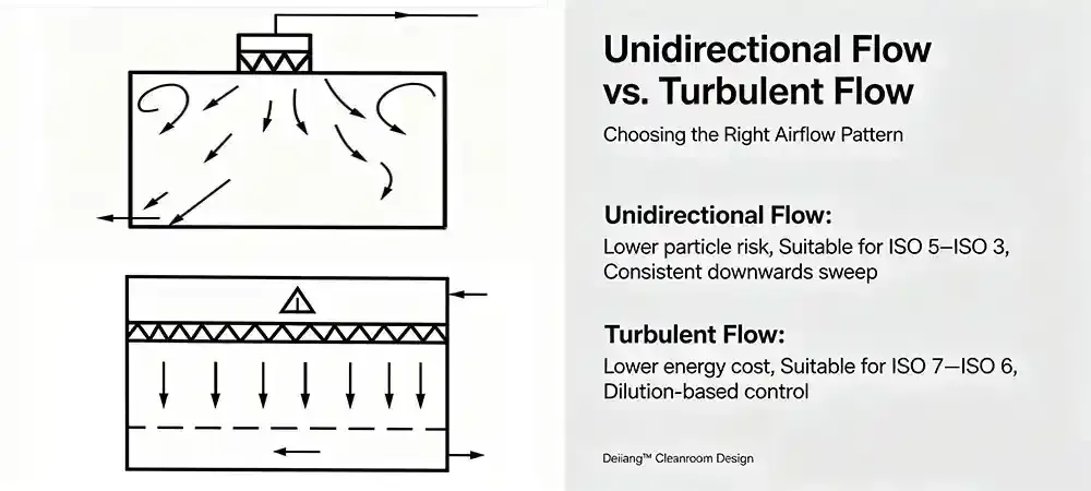
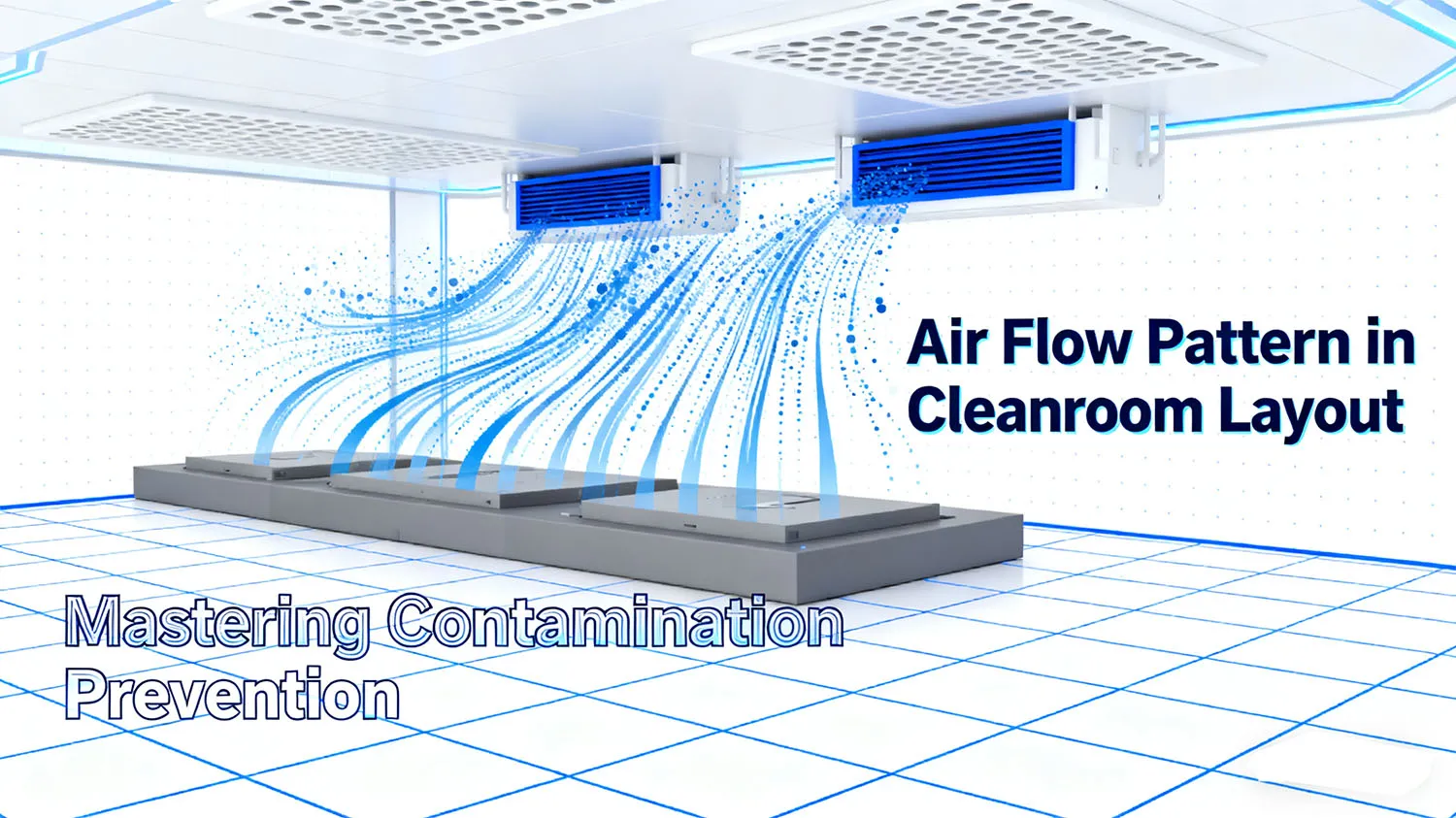
Cleanroom airflow patterns split into unidirectional and non‑unidirectional (mixed). Laminar flow design is often used synonymously with unidirectional, while turbulent airflow is a valid dilution strategy.
Quick GMP Grade ↔ ISO Mapping
*According to EU GMP Annex 1 (2022), Grade A requires unidirectional airflow at 0.36–0.54 m/s.
Air moves uniformly (usually vertical) across the critical zone, sweeping particles away. Filter face velocity is typically 0.45 m/s ±20% per ISO 14644‑4 – but note: this is measured at the filter face. At the working plane (product height), velocity decays to 0.36–0.45 m/s due to diffusion and obstructions; as long as it stays ≥0.36 m/s, the unidirectional sweep is considered effective.
Dilution-based: supply diffusers mix air, returns remove contaminants. ACH: 15–60. Suitable for background zones (ISO 7‑8), gowning, general assembly.
⚠️ Common pitfall: Installing return grilles high on the wall or ceiling in mixed‑flow rooms creates stagnant zones near the floor. Always use low‑side returns (≤0.5 m above floor) to prevent dead zones.
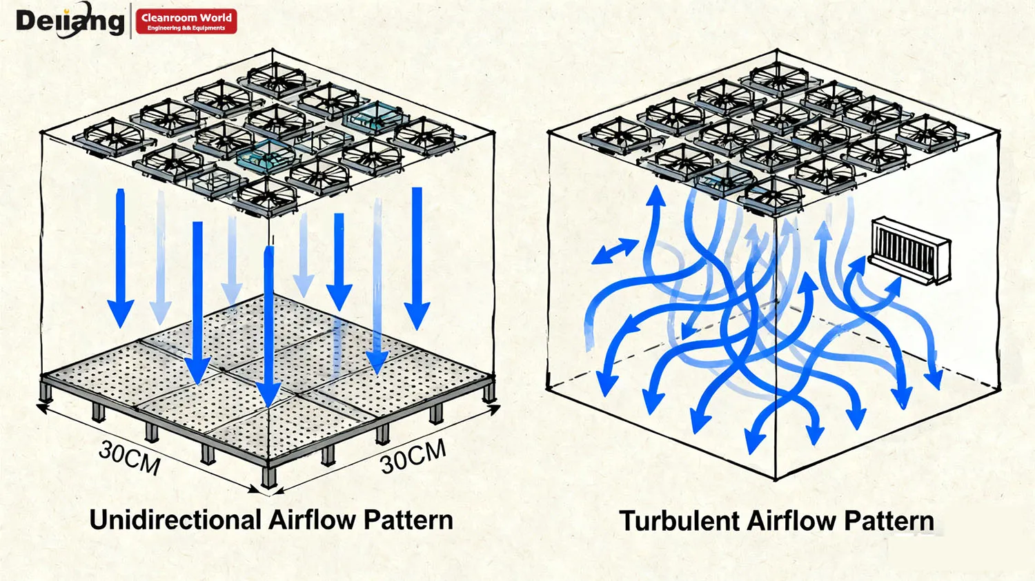
Laminar flow design is often over‑specified. Decision factors: contamination path, product exposure, and operational dynamics. Turbulent airflow with high ACH may suffice for lower‑risk zones.
CAPEX vs. OPEX – The Financial Reality
Full unidirectional (FFU‑based) costs 3–5× more in energy consumption than mixed flow, due to full‑coverage HEPA and higher fan static pressure. A typical 100 m² ISO 5 unidirectional zone can consume 150–200 kW, whereas the same area with ISO 7 mixed flow uses 40–50 kW.
Over‑designing (using unidirectional where mixed suffices) can add $100–200k annual OPEX for a mid‑size facility. Always validate with risk assessment and ISO 14644‑3 recovery tests before committing to full unidirectional.
| Factor | Unidirectional | Mixed |
|---|---|---|
| Goal | Predictable sweep | Dilute & exhaust |
| Typical areas | ISO 5+ (filling) | ISO 7‑8 (background) |
| Advantage | Strong protection | Lower cost / flexible |
| Limitation | Energy, layout‑sensitive | Dead‑zone risk |
Exposed products, sterility critical, sweep required.
Lower exposure, well‑diluted returns, cost‑conscious.
“The right pattern controls the actual contamination pathway, not just the airflow volume.”
Laminar flow design success depends on more than filters. Real cleanroom airflow patterns are shaped by five factors, all verified by ISO 14644‑3 visualization.
Deiiang™ Design Data
*Industry average power density: ~0.55 W/CFM. Deiiang™ EC‑VFD systems achieve<0.35 W/CFM, reducing annual OPEX significantly.
Identify exposure; design sweep.
Deiiang™ runs computational fluid dynamics (CFD) before installation to predict wake and thermal effects – cutting physical rework by up to 90%.
Hot equipment (e.g., sterilising tunnel) generates rising plumes that can overpower 0.45 m/s downflow – assess heat load and adjust velocity or reposition.
Pull contaminants away.
Dynamic effects; verify with smoke (including arm movements). Deiiang™ EC fans maintain stable airflow under variable loads.
ISO 14644‑3 visualization reveals actual airflow behavior—recirculation, dead zones, and cross‑contamination risks. It complements particle counting.
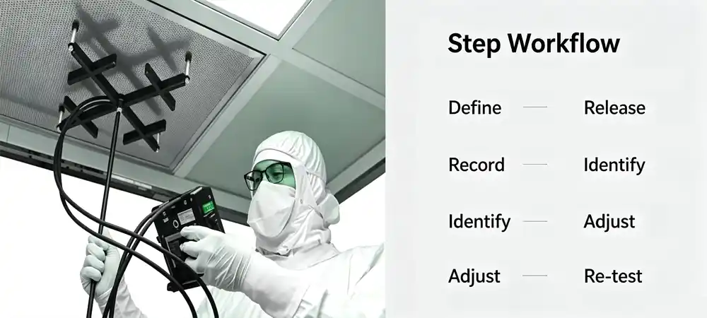
“Drawings show intent; smoke shows reality.”
Industry: Pharma (sterile injectables) | Grade: ISO 5 filling / ISO 7 background | Scope: FFU re‑layout + smoke testing.
Challenge: New equipment created wake regions and thermal plumes from a sterilising tunnel, disrupting unidirectional canopy; smoke showed recirculation.
Solution: Deiiang™ shifted 12 FFU modules (+600mm coverage), repositioned side returns, and upgraded to EC fan with closed‑loop VFD – achieving 28.5% annual energy savings compared to the original AC fan system. Smoke tests (at‑rest + in‑operation) confirmed restored ISO 5 protection.
Persona: Alex, Pharma Engineer. Planning a sterile expansion.
Is laminar flow the same as unidirectional?
In cleanroom engineering, yes—but true laminar is an idealization. Unidirectional is the correct term.
Is turbulent airflow bad?
No. Turbulent airflow is valid for background zones if designed with low‑side returns and verified recovery time.
When to use unidirectional?
Exposed products, sterile operations (Grade A/B), or surfaces highly sensitive to particles.
What does ISO 14644‑3 show?
Actual airflow paths, recirculation, dead zones, operator‑induced disruption, and thermal plume effects.
Can smoke replace particle counting?
No. Smoke validates behavior; particle counting measures cleanliness. Both are complementary.
Need airflow validation, GMP compliance, CFD simulation, or energy‑efficient FFU solutions? Share your cleanroom plans with Deiiang™. We’ll help you choose, verify, and optimise the right pattern.
Product Designer: Jason.peng | Deiiang™ Cleanroom Solutions
Introduction: Cleanroom's "Lifeline" - AirflowEffective Cleanroom

The speed regulation function of a DC fan Filter Fan Unit (FFU) is implemented through various methods, primarily utilizing electronic controls that manage the ...
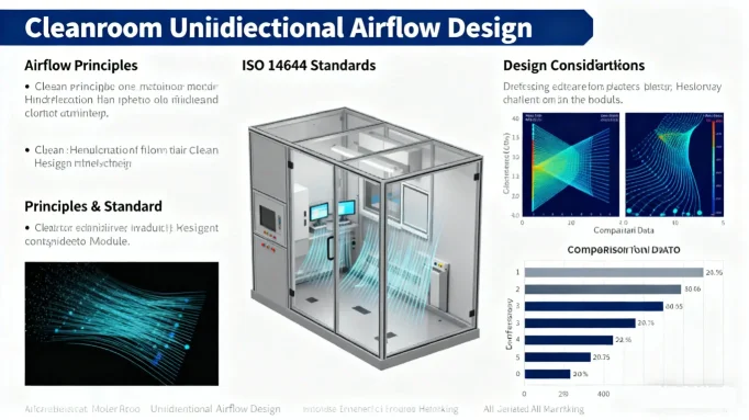
Introduction:Cleanrooms play a critical role in modern industries such as semico

Your safety relies on physics, not magic. We explain the engineering controls th
Biological Safety Cabinets vs Laminar Airflow WorkbenchesUnderstanding the criti
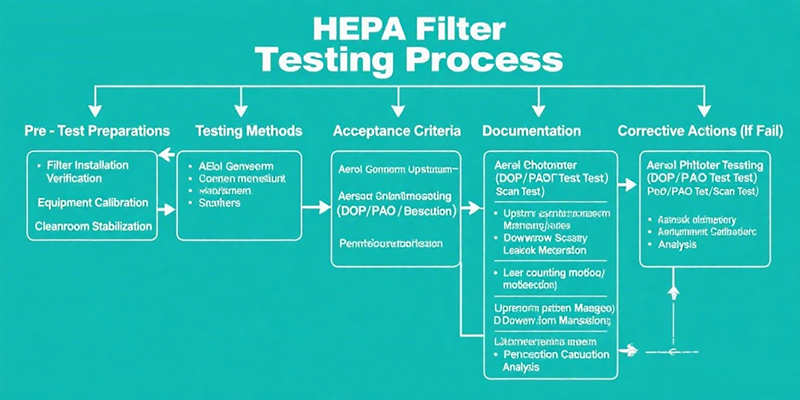
Cleanroom testing is critical and covers HEPA filter integrity, lighting, vibrat
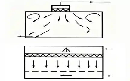
Unidirectional: best for exposed products / sterile zones (ISO 5 / Grade A/B). Creates predictable sweep. Mixed (turbulent): cost‑effective for background area...
Introduction: The Foundation of Cleanroom performanceEffective cleanroom air flo