+86 13638632902
 Jason@cleanroomequips.com


 MENU
MENU
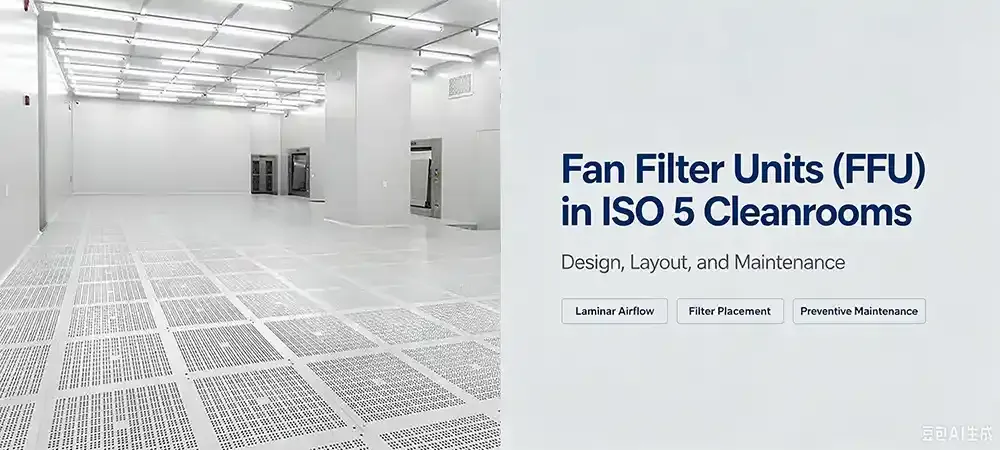
iso 5 cleanrooms provide ultra-clean controlled environments essential for semiconductors, pharmaceuticals and biomedical research, requiring extremely low airborne particle levels to avoid contamination. fan filter units (ffus) serve as the key terminal purification equipment in iso 5 cleanrooms, delivering stable laminar airflow and efficient particle filtration. Proper FFU design, reasonable layout and routine maintenance are vital to sustaining consistent cleanliness, uniform airflow and stable operational performance of ISO 5 cleanrooms. This article summarizes the key design points, layout principles and standardized maintenance strategies of FFUs, aiming to support reliable and cost-effective operation of ISO 5 cleanroom systems.
TL;DR — What matters most for ISO 5 FFU design:
- Coverage, not count: A uniform array with 60–80% ceiling coverage is more critical than simply adding more units.
- Airflow uniformity: Target ≤±15% deviation across the working plane to maintain unidirectional flow.
- Choose the right filter: ISO 5 typically requires H14 or U15 grade filters (≥99.995% efficiency at 0.3 µm).
- Test & verify: Certification depends on particle counts, velocity uniformity, and pressure differential — not just filter rating.
Deiiang™ FFU — Key Reference Data
- Air volume: 1500–2000 m³/h (standard models)
- Filter efficiency: H14 (99.995% @ 0.3 µm) / U15 (99.9995% @ 0.12 µm)
- Noise level: 48–62 dB(A) (EC motor models as low as 48–55 dB)
- Motor type: EC brushless DC, efficiency >85%, 30% energy saving vs AC
- Uniformity: ≤±15% airflow deviation across the face
what is an ffu and Why Does It Matter for ISO 5?
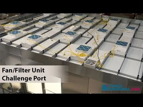
Fan Filter Units (FFUs) are stand-alone Air Cleaners in individual housings, using fans to pull air from above the ceiling in the cleanroom plenum, HEPA/ULPA filter the air and then discharge cleaned air down into the work area.
FFUs are also the primary method for achieving unidirectional flow in an ISO 5 cleanroom. Proper design of FFUs, including airflow and balance of FFUs, is crucial in achieving smooth laminar flow throughout the cleanroom to avoid creation of turbulent flow, or areas of low flow leading to cleaning-resistant contaminated areas.
FFUs and their layout, airflow characteristics and filter type determine whether a cleanroom can be operated at iso class 5 with 3,520 particles of 0.5 µm and larger per m³ of clean air.
Key Design Requirements for FFUs in ISO 5 Cleanrooms
Airflow Organization
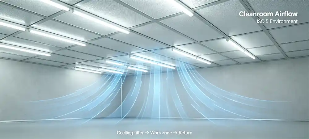
In order to satisfy the requirements for ISO 5 cleanrooms, Vertical unidirectional airflow (VUDA) is required. Air must travel in vertical parallel streams of minimal turbulence. FFU layout rates of greater than 60% are shown to be optimal for creating VUDA with inclined angles below 20°.
air changes and Coverage
An ISO 5 cleanroom typically requires 240–480 air changes per hour (ACH). That translates to replacing the entire room air every 7 to 15 seconds. To achieve this, FFU ceiling coverage should be 60–80% of the total ceiling area.
| Parameter | ISO 5 Requirement | Impact on Design |
|---|---|---|
| Air changes per hour | 240–480 ACH | Determines total airflow and FFU count |
| Ceiling coverage | 60–80% | Dictates FFU spacing and array density |
| Airflow uniformity | ≤±15% deviation | Requires careful layout and balancing |
| Filter grade | H14 / U15 | Ensures particle capture efficiency |
FFU Count & Airflow Calculation — A Practical Formula
Determining the number of FFUs for an ISO 5 cleanroom is a straightforward but critical step. The following formula gives you a first-pass estimate:
Where:
N = number of FFUs required
V = room volume (m³)
ACH_target = target air changes per hour (e.g., 300 for ISO 5)
Q_FFU = rated airflow per FFU (m³/h)
η = efficiency factor (0.85–0.95, accounting for filter loading and duct losses)
Example — 100 m² ISO 5 cleanroom with 3 m ceiling height:
- Room volume V = 100 × 3 = 300 m³
- Target ACH = 300 (mid-range for ISO 5)
- Deiiang™ FFU rated airflow Q_FFU = 1800 m³/h (standard 1175×575 model)
- Efficiency factor η = 0.90 (conservative estimate)
- N = (300 × 300) / (1800 × 0.90) = 90,000 / 1,620 ≈ 56 units
This calculation provides a baseline. In practice, layout geometry, equipment placement, and return air paths may require additional units or zoning. Deiiang™ engineers typically add 5–10% margin for flexibility and future load changes
Interactive FFU Count Calculator
Enter your room parameters and get an instant estimate of the required number of FFUs.
Filter Choice: Glass Fiber vs. ePTFE — Critical for Semiconductor AMC
Typically, glass-fiber HEPA filters are sufficient for ISO 5 applications, such as clean rooms, pharmaceutical laboratories and hospital operating theaters. For applications in semiconductor fabs that are susceptible to airborne molecular contamination (AMC), however, special ePTFE (expanded polytetrafluoroethylene) membranes are required. These filters offer ultra-low outgassing properties and do not release organic compounds that could cause damage to photoresists or interfere with etching processes. ePTFE filters are specified by leading chip manufacturers for use in lithography areas to prevent yield loss due to volatile organic compounds (VOCs). Deiiang™ offers both filter media, with ePTFE options certified for AMC control according to SEMI F21-1102.
Noise and Energy — with Deiiang™ ROI Payback Calculation
High cleanliness does not have to mean high noise or high energy consumption. Deiiang™ FFUs with EC brushless DC motors achieve efficiency >85% and 30% energy savings compared to traditional AC motors. Noise levels can be as low as 48–55 dB(A) with EC motor technology.
ROI Payback Calculation — Deiiang™ EC vs. Conventional AC FFU
Scenario: 100 FFUs in a 24/7 ISO 5 cleanroom, industrial electricity rate $0.12/kWh.
- Deiiang™ EC motor power: 105 W at 0.45 m/s face velocity
- Conventional AC motor power: 150 W (industry average)
- Annual energy consumption difference per FFU: (150 – 105) W × 8760 h / 1000 = 394.2 kWh/year
- Annual cost savings per unit: 394.2 × $0.12 = $47.30
- Total savings for 100 units: $4,730 per year
Payback period: The incremental cost of EC motors over AC is approximately $450 per FFU (based on 2025 pricing). Payback = $450 / $47.30 ≈ 9.5 months. Even with installation overhead, full ROI is achieved within 11–12 months — after that, the facility saves $4,700+ annually for the life of the system (typical 15–20 years).
* Based on Deiiang™ 1175×575 EC FFU vs. leading AC competitor. Actual savings may vary with duty cycle and local electricity rates.
FFU Layout for ISO 5 Cleanroom: How to Do It Right
Common Layout Types
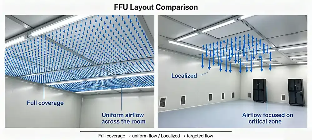
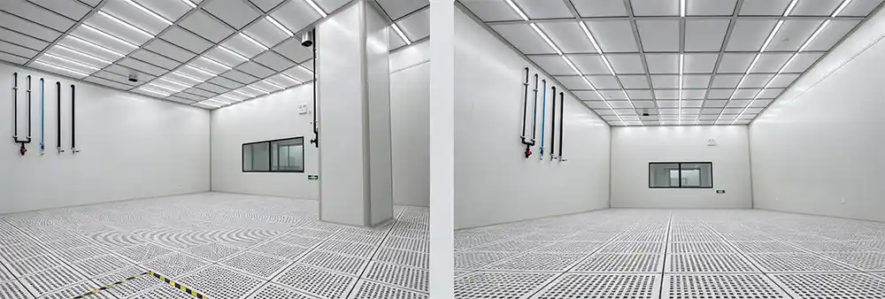
A. Full-Coverage (Ceiling-Filled) Layout
The full-coverage layout is best for very high-criticality areas (e.g. semiconductor lithography, aseptic filling areas). The coverage gives the most even distribution of air, and the easiest area to validate. Note: higher initial cost, but lowest risk of having to come back and re-configure later.
B. Zoned Coverage Layout
FFUs concentrated over the critical work zones and less FFUs in the surrounding support areas. A more flexible FFU installation in terms of cost, but it requires detailed CFD analysis to avoid any dead zones in the room.
C. Localized Workstation Coverage
Workstation Coverage: Placement of FFUs over specific pieces of equipment or work stations in a room that has already been built out. Areas that only require iso 5 classification in a room that contains areas that require a lower classification can be easily retrofitted. However, for whole-room iso 5 classification, this is not an option.
Layout Design Principles
- Maintain continuous coverage above the work zone — gaps create low-velocity zones.
- Avoid placing FFUs directly above large equipment that blocks airflow.
- Coordinate with return air openings (typically at low level or raised floor) to complete the airflow loop.
- Leave adequate clearance for filter replacement and maintenance access.
- Use CFD simulation to validate layout before installation.
Return Air Strategy: Raised Floor vs. Low-Side Wall Return
The return air path is as critical as the supply. For ISO 5 unidirectional flow, the choice between raised (grid) floor and low-side wall return directly impacts airflow straightness and particle removal efficiency.
| Feature | Raised Floor Return | Low-Side Wall Return |
|---|---|---|
| Airflow uniformity | Excellent — vertical parallel streams | Moderate — potential horizontal component near walls |
| Particle removal | Very high — downward sweep carries particles to floor | Good, but risk of particle re-entrainment near walls |
| Installation cost | Higher (raised floor structure) | Lower (wall grilles) |
| Flexibility | High — underfloor utilities and easy reconfiguration | Limited — fixed wall penetrations |
| Best for | Semiconductor, biopharma, high-precision assembly | General ISO 5 with lower ceiling height |
Key conclusion: The raised (grid) floor is generally the better choice for most ISO 5 cleanroom applications. It offers the straightest downward airflow path and allows the most efficient removal of particles by means of the floor grilles. Low-side wall return only applies in very restricted ceiling height situations (below 2.8 m) or in retrofit situations where a raised floor is not possible. For new ISO 5 cleanrooms, the raised floor is the default option.
“In ISO 5 cleanrooms, the best FFU layout is not the densest layout — it is the most balanced one.”
How Deiiang™ FFUs Support ISO 5 Design
Deiiang™ FFUs are engineered specifically for demanding cleanroom applications. Here is how the product data translates into real-world ISO 5 performance:
- Air volume: 1500–2000 m³/h per unit, allowing flexible coverage planning.
- Filter options: H14 (99.995% @ 0.3 µm) and U15 (99.9995% @ 0.12 µm) — meeting or exceeding ISO 5 requirements.
- Airflow uniformity: ≤±15% deviation across the filter face, verified by pitot-tube grid measurements.
- EC brushless DC motor: Efficiency >85%, 30% energy saving, and 50,000+ hour service life.
- Low noise: 48–62 dB(A) depending on model — suitable for operator comfort.
- Modular design: Supports group control and variable speed for precise airflow adjustment.
FFU Group Control & Communication Protocols (RS485 / Modbus / BACnet)
In an ISO 5 cleanroom with 50–200+ FFUs, individual manual adjustment of FFUs in a cleanroom is not possible. Therefore a robust group control system has to be implemented in order to be able to coordinate the fans, to monitor the fans and to alarm in case of a failure.
Deiiang™ FFUs support RS485 Modbus RTU and BACnet MS/TP protocols to connect to Building Management Systems (BMS). The key group control features are:
- Zone-based speed regulation: Adjust the speed of the FFUs in the individual zones in real-time on the basis of the particle count and process load.
- Non-operational (standby) mode: FFU’s operate at 30-50% speed during un-occupied hours to save energy while keeping positive pressure.
- Centralized fault alarming: Alert of Filter Saturation, Motor Failure, etc.
- Data logging: Record airflow, pressure drop and usage time continuously over 24 hours.
In a recent Deiiang™ project with 120 FFUs, the group control system reduced manual balancing time from 3 weeks to 4 days, and cut annual energy consumption by 22% through scheduled speed reductions during night shifts.
Deiiang™ Measured Performance Data (1175×575 EC FFU)
* Tested at 0.45 m/s face velocity, 23°C ambient, 50% RH. Individual results may vary with system configuration.
In a recent Deiiang™ project for a 12-inch wafer fab in Shenzhen, the critical lithography area used U15-grade FFUs with a design ACH of 300–320. The cleanroom passed iso 14644-1: ISO 5 validation and has been operating stably for over 18 months.
Real Project Case Study: Deiiang™ in Action
Project: Semiconductor Assembly & Test Facility -800 m² ISO 5 core area
Location: Southeast Asia
Scale: 800 m² ISO 5 core area, 120 workstations
Challenge: High equipment heat load, limited ceiling plenum height, tight 6-week installation schedule.
Deiiang™ Solution:
- Zoned FFU layout: 72% coverage over critical process areas, 55% over support zones.
- U15 filters for lithography stations, H14 for其余 areas.
- EC motor FFUs with group variable-speed control for load balancing.
- Pre-installation CFD simulation to validate airflow patterns.
- Gel-seal (fluid) ceiling grid used throughout to eliminate bypass leakage.
Validation Results (ISO 14644-1):
- PAO scan leak rate: 0% (no detectable leaks in any filter seal)
- Velocity uniformity: ±8.5% across the working plane (industry standard: ±15%)
- Particle count: ≤ 1,200 particles ≥0.5 µm/m³ (well below ISO 5 limit of 3,520)
- Pressure differential: 14 Pa maintained against adjacent ISO 7 area
Cost & Efficiency: The Deiiang™ zoned layout and gel-seal grid reduced ceiling opening modifications by 15%, saving approximately $18,000 in structural work. Annual energy savings estimated at 28% compared to AC motor baseline.
Who This Matters To: A Project Manager's Perspective
Jack — Cleanroom Project Manager
Industry: Medical device manufacturing (Southeast Asia)
Mission: Upgrade an aging 600 m² facility to ISO 5 within budget.
Pain points:
- Complex structural constraints (low ceiling, existing columns)
- Frequent equipment changes — layout must be adaptable
- Unsure how to balance coverage vs. cost
- Worried about certification failure and project delays
What Jack needs: Clear design guidelines, validated product data, reference projects, and responsive technical support.
Deiiang™ provided Jack with a zoned FFU layout proposal, CFD simulation results, and a phased installation plan. The project passed ISO 5 certification on the first attempt.
Common Misconceptions About FFUs in ISO 5 Cleanrooms
More FFUs = better cleanliness.
Overcrowding the ceiling can generate turbulence, increase energy consumption and even create more noise whilst delivering no improvement to cleaning. A well-spaced array delivering 60-80% coverage is more effective than a very densely packed array delivering 90%+ coverage but very poor spacing between lights.
HEPA/ULPA grade alone guarantees ISO 5.
While filter efficiency is fundamental to a filter, the layout, uniform airflow, pressure differences, and good seals are just as important. A good filter does not guarantee successful certification if it is integrated into a poor layout.
One layout works for all ISO 5 rooms.
Cleanrooms are generally of different dimensions and various pieces of equipment are to be positioned within them. Their heating loads as well as their specific processes all differ from one another. Hence each ISO 5 cleanroom requires a specific design of FFU (Fluorescent Fixtures) for it.
Installation is the finish line.
The Commissioning process for HEPA filters, which includes velocity mapping, particle counting, pressure testing and filter integrity scanning, demonstrates ISO 5 compliance. Ongoing maintenance and repair of filters is required to maintain ISO 5 compliance.
Thermal plumes from equipment do not affect unidirectional flow.
Deiiang™ points out that thermal plumes are created by heat-generating equipment like ovens, motors and food processors. These thermal plumes are rising columns of warm air. When in areas where FFUs are installed above heat-generating equipment, the cold air flowing downwards from the FFU collides with the thermal plume. This creates local turbulence and recirculation areas, a so-called mixing area, where particles can accumulate. For this reason Deiiang™ recommends CFD-simulations to determine the exact locations of the heat-generating equipment. The resulting FFU setup can then be adapted by offsetting the FFUs or by increasing the velocity in these specific areas.
Engineering Pitfalls — What Experienced Designers Know
⚠️ Seal Trap: Gel Seal vs. Gasket Seal
In developing countries with hot climates, many ISO 5 projects fail PAO (DOP) filter-integrity certification not because of problems with the filter media but rather due to seal leakage from the rubber compression gaskets used for the sealing of the filter frames. These gaskets tend to degrade slowly with temperature cycles and vibration from the ceiling grid above, leading to latent leaks which can cause problems later, such as during the PAO test for filter-integrity certification.
Seal leakage rather than failures in the filter media can cause a number of ISO 5 projects to fail PAO (DOP) filter-integrity certification. The rubber compression gaskets, which are commonly used to seal the filters into the ceiling grid, degrade over time due to temperature cycles and ceiling-grid vibration, resulting in latent leaks. These leaks are not visible until a test for integrity is carried out and the failure recorded.
⚠️ False Unidirectional Flow — Edge Velocity Collapse
The fact that a room achieves 80% coverage using FFUs on the ceiling does not take into account the 30cm wide perimeter zone around the walls. Here, the airflow velocity can drop by as much as 30% to 40% below the velocity in the room center, thus not meeting the unidirectional flow tests in the perimeter zone.
Edge compensation involves increasing the fan speed on perimeter FFUs by 10-15% over central units. By adding air-guide vanes to blind panels that are in close proximity to perimeter FFUs, air can be directed down on to floor to prevent stagnation. As mentioned above, edge compensation can also be used to ensure down flow is maintained.
FFU Layout Design Workflow
- Define cleanroom class & process needs — ISO 5 with unidirectional flow
- Determine the room volume and the heat output — affects number of Air Changes per Hour (ACH) and number of Filter Fans Units (FFU).
- Map return air paths — raised floor or low-level returns
- Select appropriate FFUs to cover the ceiling area of approximately 60% to 80% and specify the filter rating of H14/U15.
- Run CFD simulation to verify cleanroom uniformity and identify potential cleanroom dead zones.
- Balance individual FFU’s to obtain uniform velocity throughout the cleanroom.
- Test & Validate Cleanroom to Measure Velocity, Particle Count, Static Pressure & Filter Integrity.
- Monitor and maintain — check pressure drop and airflow on a regular basis.
Testing and Validation: Proving ISO 5 Compliance
Certifying an ISO 5 cleanroom requires a suite of tests, not just a single particle count. Here is what the validation process typically includes:
- Air velocity uniformity: Measured across the working plane, typically at 0.45 m/s ±20%. Target ≤±15% deviation.
- Particle count: ≤3,520 particles ≥0.5 µm per m³.
- Filter integrity: DOP/PAO scan testing to detect leaks in HEPA/ULPA filters and seals.
- Pressure differential: ISO 5 area must be positive relative to adjacent spaces (typically 10–15 Pa).
- Recovery test: How quickly the room returns to ISO 5 after a contamination event.
Deiiang™ provides full test documentation for every FFU shipment, including filter efficiency certificates and factory airflow uniformity data.
Maintenance and Long-Term Operation
How iso 5 clean rooms are Maintained Using FFU’s
Track filter pressure drop on a weekly basis; typical increase = 50‑100 Pa.
Quarterly Check FFU airflow (deviation ±15%); then adjust fan speed or use new filters as required.
replace HEPA/ULPA filters per manufacturer guidelines or when pressure drop doubles baseline.
Annual calibration for cleanroom controls and sensors.
⚠️ The "Hidden Dust" Trap — Pre‑Filter Bypass Leakage
The “Hidden Dust” Trap in Standard Clean Room Frames – Bypass Leakage Through Pre Filter Frames leading to early HEPA Clogging within 6-8 months. Typical frame designs have large areas of seal between the pre filter frame and the plenum around the FFU and have high amounts of dust (5% – 30%) that is bypassed around the pre filter frames and aggressively dirties the HEPA filters.
🔧 Maintenance Best Practice: Room‑Side Replaceable (RSR) vs. Plenum‑Side Replaceable (PSR)
Conventional PSR FFUs require access to ceiling-plenum, 45 minutes per filter change to service in production, huge risk of contamination.
Deiiang™ RSR FFUs can have filters changed inside a cleanroom within 12 minutes, thus there is no disruption to adjacent iso5 areas. For a 100FFU facility the annual service hours would decrease from about 75 to 20 hours. The quick-release clamp-seal interfaces of Deiiang RSR FFUs will restore performance of the FFU after reinstallation, thus no re-testing of the surrounding ISO5 areas is required.
Conclusion: FFU Design Is a System Engineering Challenge
A balanced airflow design in a FFU is more than just a stack of boxes. Coverage, uniformity, filter selection, and testing are all factors that must be balanced to achieve the required cleanliness.
Deiiang™ has vast experience in FFU design for Clean Rooms of all classifications, including successful implementations of iso 5 clean rooms for various industries, including Semiconductor, Pharmaceuticals and Medical Devices.
References
- iso 14644-1:2015 — Cleanrooms and associated controlled environments, Part 1: Classification of air cleanliness by particle concentration
- Technical Air Products — How FFU Placement Affects Particle Count and ISO Certification
- FFU Matching Guidelines for cleanroom classes: Analysis of the Latest 2025 ISO Standards and Selection Cases
- Optimizing Vertical Unidirectional Airflow in Cleanrooms — MDPI Atmosphere 2025
- IEST — Institute of Environmental Sciences and Technology (HEPA/ULPA testing standards)
Product Designer: Jason.peng | Deiiang™ — Cleanroom Technology Solutions