+86 13638632902
 Jason@cleanroomequips.com
 MENU
MENU
Executive Summary
Electromagnetic flow meters are the top choice for conductive liquids (wastewater, slurries, acids) with accuracy ±0.5% and zero pressure loss. They are widely applied in cleanroom flow measurement for DI water and chemical dosing lines.
Ultrasonic flow meters enable non-invasive, no-shutdown installation on large pipes (≥DN50) with accuracy ±1.0–2.0%, ideal for water and light hydrocarbons. This makes them a preferred option in flow meter selection for cleanrooms where process interruption must be avoided.
Among the common types of flow meters, vortex flow meters offer a cost-effective solution for steam, compressed air, and general gases/liquids with wide turndown (10:1 to 40:1) and no moving parts.
The orifice plate flow meter is used in most high-temperature, high-pressure applications. It is low in first cost, but has higher permanent pressure loss. The max parameters for this type of flow meter are temperature up to 600 °C and pressure up to 40 MPa.In the selection of flow meters for extreme conditions, they are still a reliable choice.
Thermal mass flow meters are ideal for low-flow gas measurement with direct mass reading and no need for temperature/pressure compensation (0–100 m/s).For cleanroom flow measurement of inert and process gases, they offer fast response and high turndown.
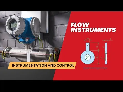
Deiiang™ recommendation: For iso 5–8 cleanrooms, prioritize low-particle-shedding materials, proper grounding (for electromagnetic), and vibration isolation (for vortex). For a reliable flow meter selection for cleanrooms, consult Jason Peng for site-specific selection matrices.
Introduction
Choosing the right flow meter for a cleanroom environment is a critical part of cleanroom flow measurement, and the selection of flow meters involves multiple performance and compatibility criteria. Cleanrooms have stringent requirements regarding particle generation, material compatibility, cleanliness, and reliability. Five common types of flow meters: electromagnetic, ultrasonic, vortex, orifice plate, and thermo-mass, each have their own advantages and limitations.
In cleanroom flow measurement, flow meters are used to monitor utilities (cooling water, DI water, chemicals), process gases (nitrogen, oxygen, clean dry air), and steam used for sterilization. Inappropriate flow meter selection for cleanrooms will lead to contamination, cause measurement drift, or require frequent maintenance, all of which can jeopardize the integrity of the cleanroom. This guide provides a systematic framework to help you selecting among five common types of flow meters in light of fluid characteristics, pipe size, accuracy requirements, and installation constraints.
With over 15 years of experience in cleanroom instrumentation, Deiiang™ has developed a data-driven methods to flow meter selection for cleanrooms. Jason Peng, Our product designer has collated performance benchmarks, best installation practices, and local compliance data to help engineers make informed decisions. This article integrates Deiiang™'s proprietary test results and field data to quantify the advantages and disadvantages among five common types of flow meters.
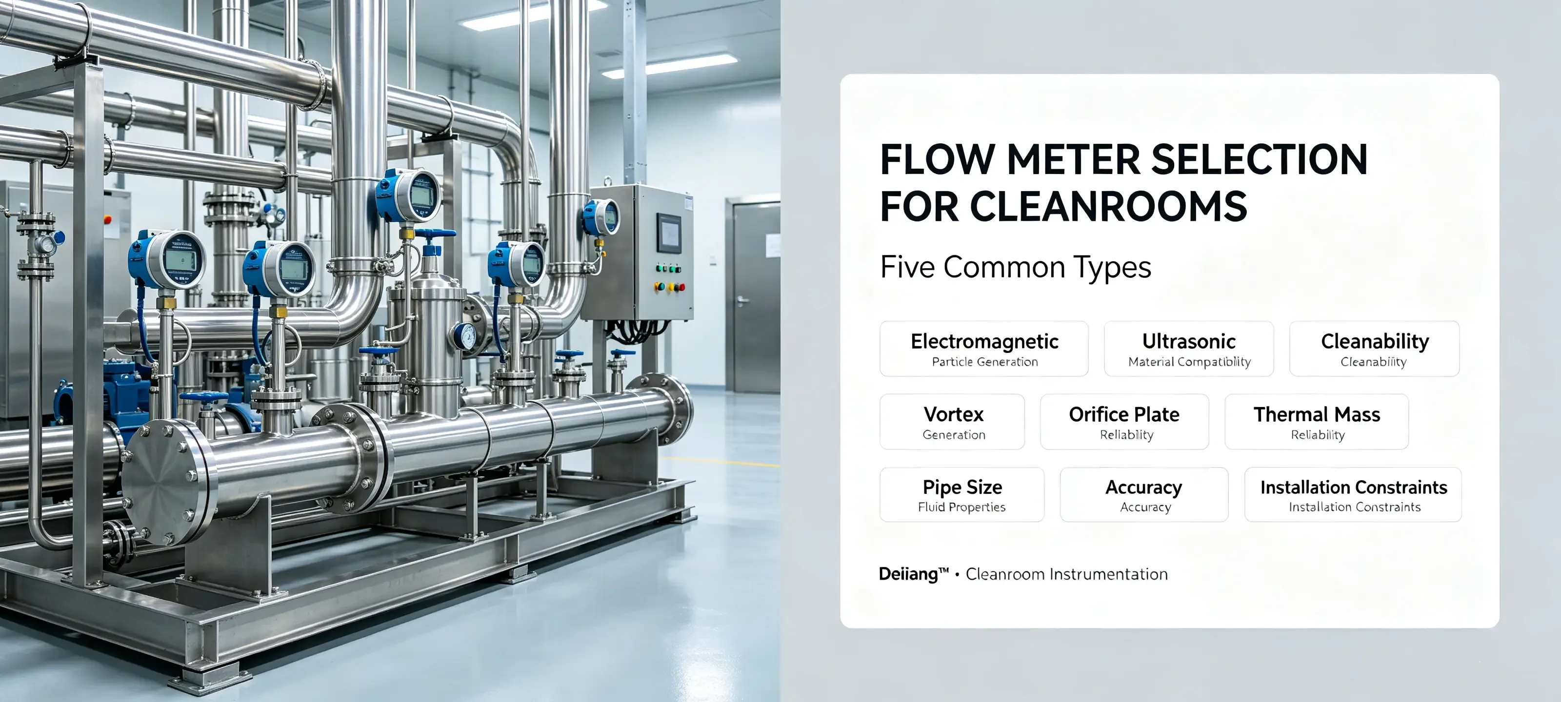
Overview of the Five Common Types of Flow Meters for Cleanroom Flow Measurement
The flow meter selection for cleanrooms begins with understanding the fundamental operating principles and application envelopes of different types of flow meters. Below is a high-level comparison of the five technologies:
| Flow Meter Type | Principle | Typical Accuracy | Fluid Compatibility | Pipe Size Range |
|---|---|---|---|---|
| Electromagnetic | Faraday's law (conductive fluids) | ±0.5% of reading | Conductive liquids, slurries | DN10 – DN3000 |
| Ultrasonic | Transit-time / Doppler | ±1.0 – 2.0% | Liquids, gases (with limits) | DN25 – DN6000+ |
| Vortex | Kármán vortex street | ±0.75 – 1.5% | Liquids, gases, steam | DN15 – DN500 |
| Orifice Plate | Differential pressure (Bernoulli) | ±0.5 – 1.0% | Liquids, gases, steam | DN25 – DN1200 |
| Thermal Mass | Heat dissipation (hot-wire) | ±1.0 – 2.5% | Gases only | DN6 – DN300 |
Each of the five common types of flow meters has a unique sweet spot. The following sections dive deep into the working principles, performance metrics, installation requirements, and application case studies for each technology, with specific Deiiang™ product references and field data that support cleanroom flow measurement.
1.Electromagnetic Flow Meter
Working Principle
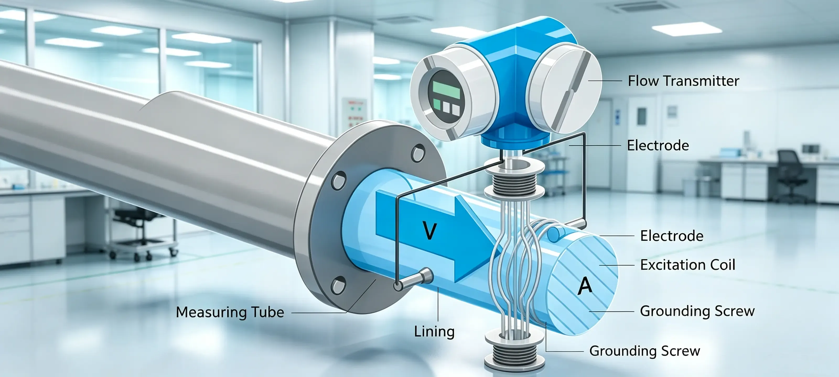
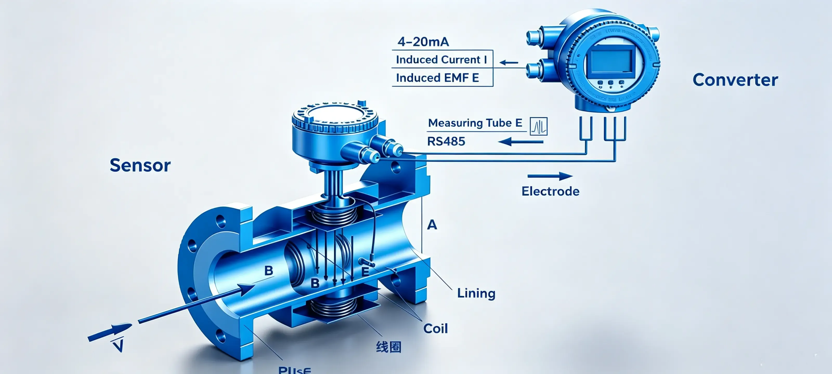
The electromagnetic flow meter, one of the most widely used types of flow meters in cleanroom flow measurement, operates on Faraday's law of electromagnetic induction: when a conductive fluid flows through a magnetic field, an electromotive force (EMF) is induced perpendicular to both the flow direction and the magnetic field. The induced EMF is directly proportional to the average flow velocity.
Formula: E = k × B × D × v (where E = induced voltage, k = constant, B = magnetic flux density, D = pipe diameter, v = average velocity). The volumetric flow rate Q = v × A, where A is the cross-sectional area.
This technology is inherently non-intrusive—there are no moving parts or obstructions in the flow path, making it ideal for cleanroom flow measurement where particle generation must be minimized.
Pros & Cons
✔ Advantages
No pressure loss — energy efficient for large pipes
High accuracy (±0.5%) and wide turndown (up to 100:1)
Unaffected by temperature, pressure, or viscosity changes
Measures slurries, corrosive media, and particle-laden fluids
Simple construction, low maintenance, no moving parts
✖ Disadvantages
Fluid must be electrically conductive (>5 µS/cm)
Cannot measure gases, oils, or ultra-pure water
Limited to moderate temperatures (<200 °C) and pressures
Sensitive to electromagnetic interference; requires proper grounding
Liner materials (PTFE, rubber) may wear with abrasive slurries
Typical Applications in Cleanrooms
Water and wastewater treatment (cooling water, process water)
Chemical dosing and acid/alkali transfer (HCl, NaOH, H2SO4)
Slurry and pulp handling in pharmaceutical intermediates
Food-grade slurries and sanitary applications (with hygienic liners)
Mining and metallurgical slurries where particle content is high
Deiiang™ offers the DE-EMF series with PTFE liners and Hastelloy electrodes, specifically designed for aggressive chemical environments in ISO 7–8 cleanrooms. Jason Peng's team has validated the DE-EMF series against iso 14644-3 particle shedding tests, showing 0.3 particles/cm³ release during normal operation, making it a safe choice in any selection of flow meters for cleanroom facilities.
Installation Guidelines
Straight pipe requirements: Upstream ≥5D, downstream ≥5D (where D = pipe diameter). If upstream has a valve: ≥10D; if upstream has a pump: ≥20D.
Full-pipe operation: Must be installed in a vertical or horizontal pipe that remains completely filled with fluid. Avoid air pockets and partial-fill conditions.
Grounding: Proper grounding of the flow tube and fluid is important to prevent damage from stray current.Use grounding rings or electrodes as recommended.
Avoid strong electromagnetic fields: Keep distance from motors, VFDs, and transformers. Use shielded cables and separate cable trays.
Orientation: Horizontal installation with electrodes in the horizontal plane (not at the top or bottom) prevents air bubbles from accumulating at the electrodes.
Temperature & pressure: Specify materials for liner and electrodes to ensure integrity at the process temperature. High temperature liners are available (e.g. PFA).
2. Ultrasonic Flow Meter
Working Principle
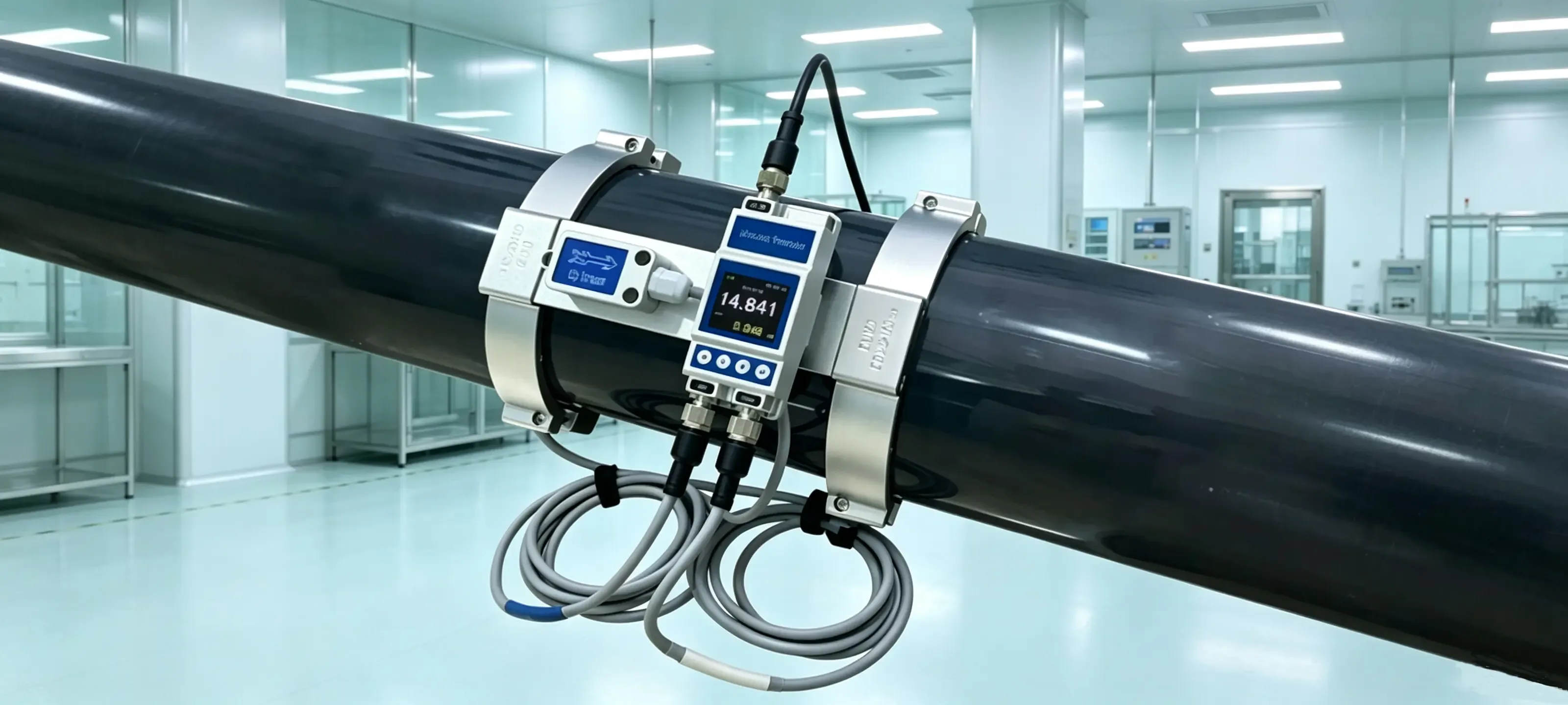
Cleanroom flow meters often use ultrasonic flow measurement. This technique uses acoustic waves and there are two methods of measuring the flow.
Transit-time (time-of-flight): Ultrasonic pulses are sent alternately upstream and downstream. The difference in transit time is proportional to the average flow velocity. This method works best with clean liquids and gases.
Doppler: High-frequency sound waves are reflected by particles or bubbles in the fluid. The frequency shift is proportional to the flow velocity. This method is suitable for dirty or aerated fluids.
Even cleanroom flow measurement can be done non-invasively with clamp-on transducers for either method of permanent or temporary measurement, without interfering with the cleanroom’s operations.
Pros & Cons
✔ Advantages
No process shutdown required for clamp-on installation
Zero pressure loss, no media contamination
Can measure both liquids and gases (transit-time)
Suitable for very large pipe diameters (DN6000+)
Portable versions enable spot-checking and verification
No moving parts, long operational life
✖ Disadvantages
Accuracy degrades with high gas content (>2% entrained air) or heavy solids
Requires long straight pipe runs (≥10D upstream, ≥5D downstream)
Pipe scale, corrosion, or thick liners attenuate the signal
Small pipe diameters (<DN25) and low velocities (<0.3 m/s) reduce accuracy
Vibration and acoustic noise from pumps or valves can interfere
Typical Applications in Cleanrooms
Chilled water and cooling water distribution networks
Long-distance water transmission pipelines
Crude oil and hydrocarbon flow measurement
Clean water and DI water monitoring
Gas pipelines (with stable pressure and dry gas)
Routine verification of other flow meters (portable clamp-on)
Deiiang™ provides the DE-US series clamp-on ultrasonic flow meters with dual-channel sensors for enhanced accuracy. In a recent cleanroom cooling water application, the DE-US series achieved ±1.2% accuracy over a flow range of 50–1500 m³/h, with zero downtime during installation. Product designer Jason Peng recommends the DE-US series for ISO 5–8 environments where non-invasive cleanroom flow measurement is a priority.
Installation Guidelines
Straight pipe requirements: Upstream ≥10D, downstream ≥5D. Best performance is achieved with transducers located at a distance of at least 10D from any bends, valves or reducers.
Surface preparation: Degrease pipe surfaces and remove all rust, scale, and paint.. Apply acoustic coupling gel between the transducers and the pipe.
Avoid welded seams and supports: Transducers should be positioned at a distance of at least 300 mm from pipe welds, flanges and pipe supports in order to ensure a sufficient acoustic contact.
Signal quality: Use the meter’s signal strength indicator to ensure there is sufficient acoustic coupling.Signal attenuation should be < 80% of the transmitted amplitude.
For gas measurement: Ensure the gas is dry and particle-free. Pressure must be stable (variation < 10%). Use specialized gas-rated transducers.
Avoid two-phase flow: Installation is NOT RECOMMENDED on pipelines with boiling liquid, condensate flashing or entrained gases in excess of 2% volume.
3. Vortex Flow Meter
Working Principle
As a versatile option among types of flow meters for steam and gas, the vortex flow meter is based on the Kármán vortex street phenomenon. When fluid flows past a bluff body (shedder bar), alternating vortices are generated downstream. The frequency of vortex shedding is directly proportional to the fluid velocity:
f = (St × v) / d where f = vortex frequency, St = Strouhal number (dimensionless), v = fluid velocity, d = width of the bluff body.
The frequency is detected by a piezoelectric sensor or capacitive sensor, and the volumetric flow rate is calculated from the velocity and pipe cross-sectional area. Vortex meters are versatile, measuring liquids, gases, and steam with a single device, simplifying the selection of flow meters for mixed-utility cleanrooms.
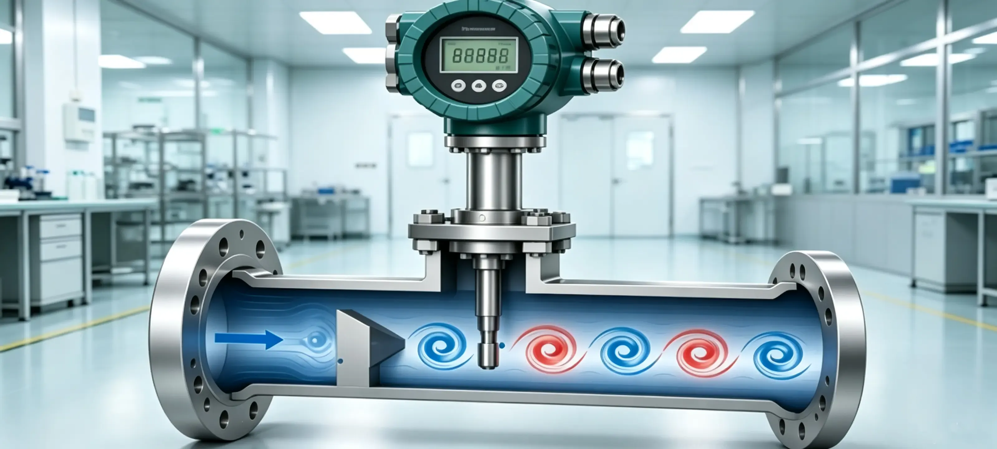
Kármán vortex street behind a bluff body (source: Deiiang™)
Pros & Cons
✔ Advantages
Simple, robust construction with no moving parts
Wide turndown ratio (10:1 to 40:1) with moderate accuracy
Measures liquids, gases, and steam in one device
Low pressure drop compared to orifice plates
Cost-effective, suitable for medium to high pressures
Digital output with temperature/pressure compensation available
✖ Disadvantages
Poor performance at low flow rates (vortex shedding ceases below Reynolds number ~10,000)
Vibration-sensitive; pipe vibration can create false signals
Not suitable for highly viscous or slurry fluids (blockage risk)
Temperature limited by sensor electronics (typically<350 °C)
Requires straight pipe runs to ensure stable velocity profile
Typical Applications in Cleanrooms
Saturated and superheated steam measurement for sterilization
Compressed air and nitrogen distribution monitoring
General process liquids (water, solvents, chemicals)
HVAC and thermal utility networks
Fuel gas and natural gas measurement
The Deiiang™ DE-VF series vortex flow meters feature a patented dual-sensor design that rejects pipe vibration up to 2g. In a cleanroom steam sterilization application, the DE-VF series achieved ±0.8% accuracy at 180 °C saturated steam, with a turndown of 30:1. Jason Peng's team recommends the DE-VF for ISO 6–8 facilities where steam and compressed air are the primary utilities, supporting reliable cleanroom flow measurement.
Installation Guidelines
Straight pipe requirements: For typical installations: Upstream ≥ 15D, Downstream ≥ 5D. For installations with Upstream Valves or Pumps: Extend Upstream measurement to ≥ 20D.
Vibration isolation: In general, mounting a meter on a section of pipe that has mechanical vibration is to be avoided. Use of vibration-damping type mounts or separate meter support is suggested.
Orientation: For gas/steam service, a horizontal installation with the meter body uppermost is preferred. For liquid service, install vertically in the pipe with flow upwards to prevent air entrapment.
Valve selection: Upstream and downstream of a block and bleed valve use full bore gate valves or ball valves and avoid globe valves or butterfly valves as these create flow disturbances.
Fluid cleanliness: In field installation, a strainer or filter should be installed upstream of the bluff body to protect it from large solids that could cause damage.
Temperature range: The sensor electronics must be within specified temperature limits. Use a remote-mounted transmitter for high-temperature steam service.
4. Orifice Plate Flow Meter (Differential Pressure)
Working Principle
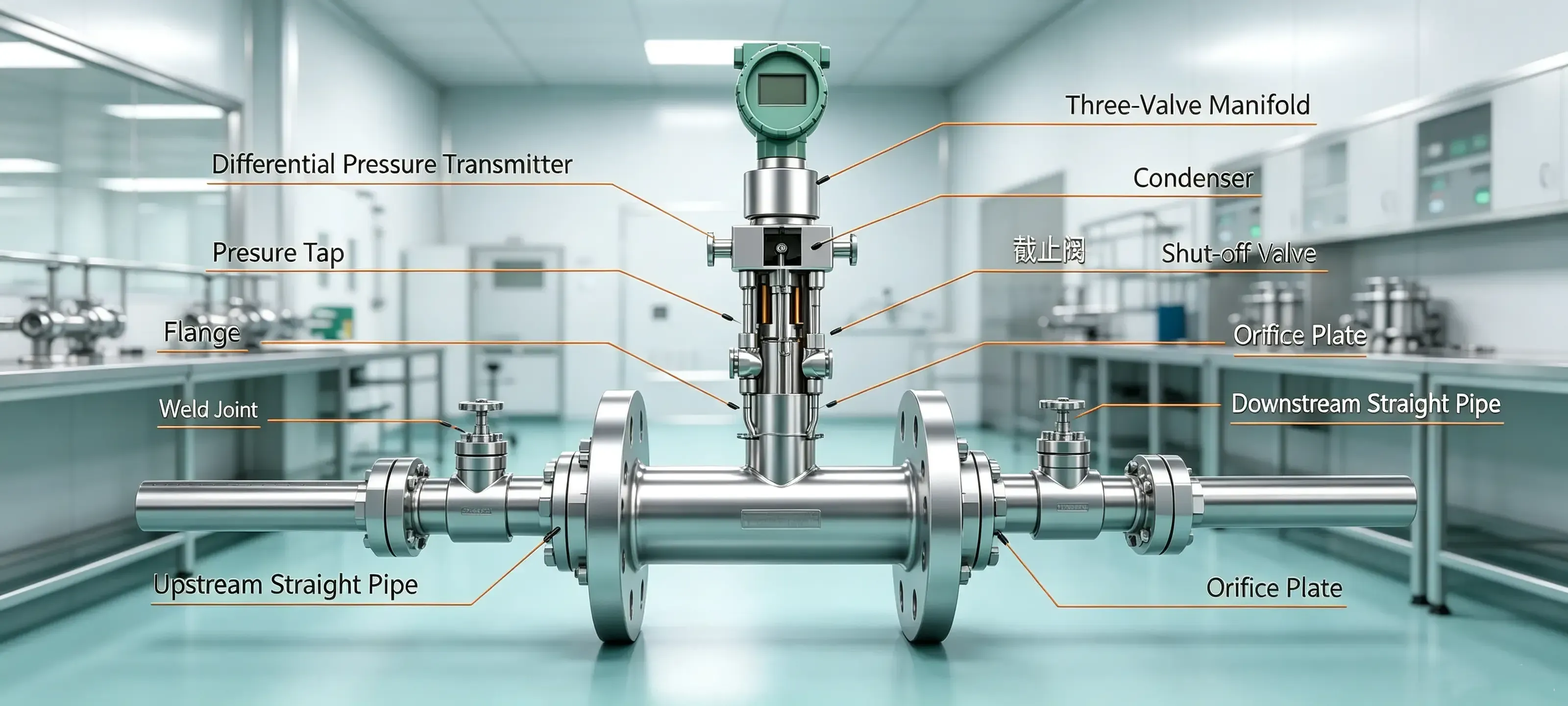
In the selection of flow meters for high-pressure and high-temperature cleanroom utilities, the orifice plate flow meter is a classic differential pressure (DP) device based on Bernoulli's equation. As fluid passes through a constriction (orifice plate), the velocity increases and the static pressure decreases. The pressure difference between the upstream and downstream tapping points is measured and correlated to flow rate:
Q = C × Y × (π/4) × d² × √(2 × ΔP / ρ)
where Q = volumetric flow, C = discharge coefficient, Y = expansion factor, d = orifice diameter, ΔP = differential pressure, ρ = fluid density.
Orifice plates are simple, rugged, and well-understood, with decades of industry experience. Standard orifice plates (ISA 1932, ISO 5167) do not require individual calibration if manufactured to specification.
Pros & Cons
✔ Advantages
Simple, robust construction with no moving parts
Low initial cost, especially for large diameters
Proven technology, standardized (ISO 5167, ASME MFC)
Can handle high temperatures (up to 600 °C) and high pressures (up to 40 MPa)
Wide fluid compatibility: liquids, gases, steam, two-phase
No power required at the primary element
✖ Disadvantages
Significant permanent pressure loss (energy cost)
Narrow turndown ratio (typically 3:1 to 4:1)
Poor accuracy at low flow rates (square-root relationship)
Edge wear and fouling reduce accuracy over time
Very long straight pipe requirements (≥20D upstream)
Installation footprint is large; requires impulse lines
Typical Applications in Cleanrooms
High-pressure steam and gas pipelines in petrochemical plants
Thermal power generation and utility steam metering
Legacy industrial networks where orifice plates are already installed
Bulk liquid and gas custody transfer (with proper calibration)
High-temperature hydrocarbon and chemical process streams
Deiiang™ manufactures the DE-OP series orifice plates with advanced coatings (Tungsten Carbide, Ceramic) to resist erosion and corrosion. In a high-temperature steam application (450 °C, 6 MPa), the DE-OP series maintained ±0.8% accuracy over a 12-month period, with wear rates 60% lower than uncoated plates. Jason Peng recommends the DE-OP for ISO 7–8 cleanrooms with existing DP infrastructure, offering a proven path in the selection of flow meters for demanding conditions.
Installation Guidelines
Straight pipe requirements: Upstream of ≥20D and downstream of ≥10D (for standard Concentric Orifice Plates). 30D upstream and 15D downstream for best accuracy.
Plate orientation: The beveled edge of the orifice plate is sharpened on the upstream side. The downstream side is flat or very slightly chamfered.
Pressure tapping: Liquids should be tapped on the side (horizontally) in order to avoid having any sediment or air in the sample. Gases should be tapped on top, while steam should be tapped on the side with a condensate pot.
Impulse lines: Slope impulse lines downward (for gases) or upward (for liquids) to prevent accumulation of condensate or gas bubbles. Use equal-length impulse lines for both high and low ports.
Seal pots and manifolds: For steam and corrosive fluids, use seal pots to protect the differential pressure transmitter from high temperatures and corrosive media.
Routine inspection: Occasionally remove the orifice plate and inspect the edge for wear and fouling. Clean or replace as required.
5. Thermal Mass Flow Meter
Working Principle
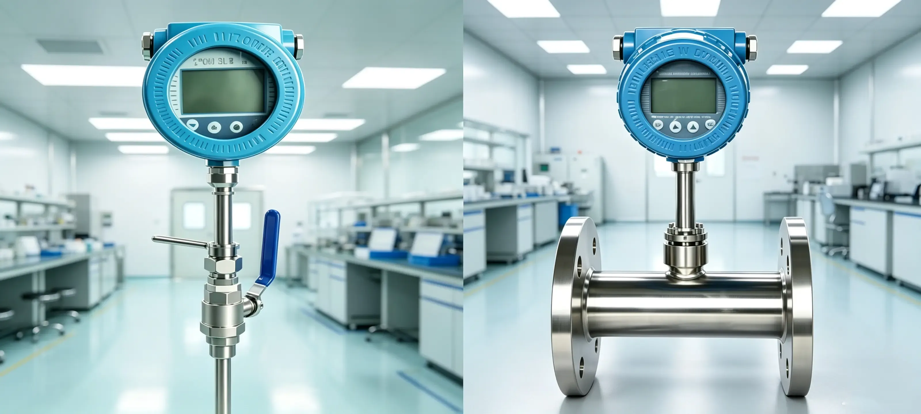
For cleanroom flow measurement of gases, thermal mass flow meters measure flow rate based on heat transfer from a heated sensor to the flowing fluid. Two common techniques exist:
Constant power (hot-wire): A fixed amount of heat is supplied to a sensor, and the temperature difference between the heated and reference sensors is measured. The temperature difference is inversely proportional to the mass flow rate.
Constant temperature (thermal dispersion): The sensor is maintained at a constant temperature above the fluid temperature. The electrical power required to maintain this temperature is proportional to the mass flow rate.
A thermal meter directly determines mass flow (and not volume flow) and is used almost exclusively for gas measurement. There is no need for any temperature- or pressure-compensation, which simplifies the choice of a flowmeter for gas measurement in cleanrooms.
Pros & Cons
✔ Advantages
Direct mass flow measurement — no temperature/pressure compensation needed
Excellent low-flow sensitivity (down to 0.1 m/s)
Very low pressure drop (no obstructions in the flow path)
Wide turndown ratio (up to 100:1)
Fast response time (milliseconds)
Compact design, ideal for small pipes
✖ Disadvantages
Primarily for gases; liquid and steam performance is poor
Sensor probe can be fouled by dust, oil mist, or condensate
Accuracy depends on gas composition; changes in specific heat cause errors
Limited to moderate temperatures (<200 °C) and pressures
Not suitable for corrosive or wet gases without special coatings
Typical Applications in Cleanrooms
Compressed air and nitrogen distribution monitoring
Natural gas and biogas flow measurement
Oxygen and inert gas supply lines
Exhaust and flue gas monitoring
Laboratory and analytical instrument gas supply
Micro-flow gas metering (e.g., gas chromatography)
Deiiang™ offers the DE-TMF series thermal mass flow meters with a patented self-cleaning sensor design. In a cleanroom compressed air application, the DE-TMF series achieved ±1.2% accuracy over a flow range of 0.5–50 Nm³/h, with a turndown of 100:1. Jason Peng's team has validated the DE-TMF series against iso 8573-1 for compressed air quality, with particle shedding below 0.1 particles/cm³ at 0.3 µm, ensuring safe cleanroom flow measurement.
Installation Guidelines
Straight pipe requirements: Upstream of ≥10D and downstream of ≥5D. For an insertion Thermal Mass Flowmeter, upstream of ≥15D for best accuracy.
Sensor orientation: Horizontal or vertical probe installation must be fully immersed in the flow stream. Care must be taken to avoid installation at the top of horizontal pipes as condensate may drip onto the sensor.
Flow direction: Check that the flow arrow on the meter body is in the correct flow direction. Most thermal meters are bi-directional but meter accuracy is best in the meter’s designated flow direction.
Avoid wet gas: Do not install thermal meters in gas streams with condensate droplets or high humidity (>95% RH). Use a filter/dryer upstream to remove liquid water.
Gas composition: The meter must be calibrated for the specific gas composition (or mixture). For variable composition gases, use a gas analyzer in conjunction with the flow meter.
Cleaning: Periodically remove the sensor probe and clean it with a soft brush and appropriate solvent to remove any accumulated deposits.
💡 Deiiang™ tip: For cleanroom gas applications with varying compositions, specify the DE-TMF-MIX version with integrated gas correction factors for up to 8 different gases. The meter automatically switches correction factors based on user-defined gas selection.
Comparison Matrix: Five Common Types of Flow Meters for Cleanroom Flow Measurement
This side-by-side comparison aids in the selection of flow meters for cleanroom applications, evaluating the five common types of flow meters based on key performance indicators. The scores are based on Deiiang™ internal testing and field data.
Installation and Acceptance Key Points
Proper installation is critical for achieving the stated accuracy and reliability in cleanroom flow measurement with any of the five common types of flow meters. The following guidelines are applicable across all flow meter technologies in cleanroom environments, and the selection of flow meters should always consider installation constraints.
General Installation Checklist
Please ensure the flow meter's installation direction matches the flow direction arrow on the valve body.
Please ensure the straight pipe length meets the manufacturer's minimum requirements for this specific flow meter type.
Ensure the pipe is filled with fluid and free of air bubbles.
For electromagnetic flow meters: Ensure proper grounding and shielding to avoid electromagnetic interference.
For ultrasonic flow meters: After applying acoustic coupling agent, confirm the signal strength is ≥80%.
For vortex flow meters: If pipe vibration exceeds 1g, install a vibration damper.
For orifice plate flow meters: Ensure the sharp edges face upstream and the pulse line is tilted at an appropriate angle.
For thermal mass flow meters: Ensure the gas is dry and the sensor probe is clean.
Record the baseline value after zero-flow calibration.
Document pipe cross-sectional details, commissioning data, and installation process with photographs.
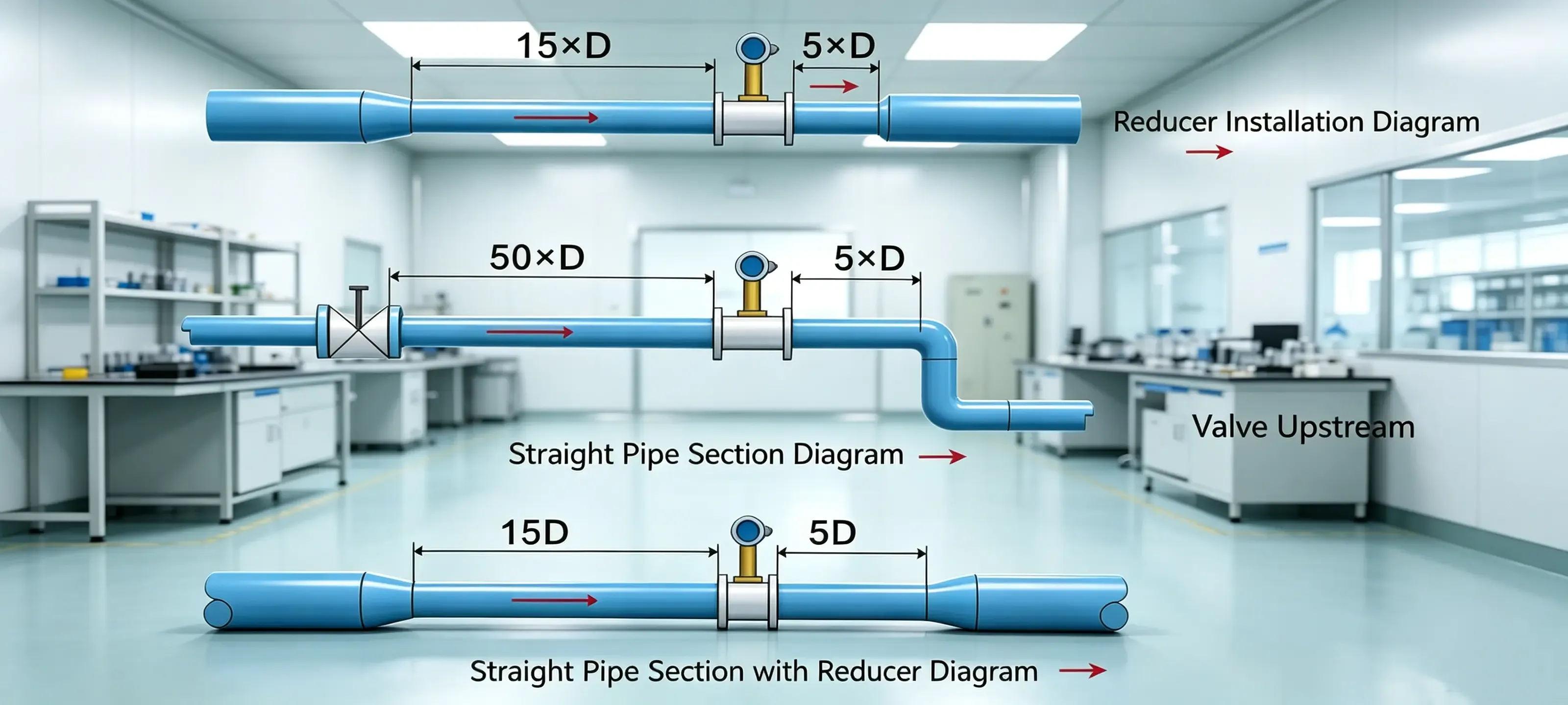
Acceptance Testing
Leak test: Pressurize the system to 1.5× the operating pressure and verify no leaks at flanges, fittings, or meter connections.
Electrical test: Verify the meter's output signal (4–20 mA, pulse, or digital) matches the expected values at known flow conditions.
Accuracy verification: Use a portable reference flow meter (e.g., clamp-on ultrasonic) to spot-check accuracy at 3–5 flow points.
Particle shedding test: For cleanroom installations, perform a particle count test (ISO 14644-3) upstream and downstream of the meter to ensure no contamination is introduced.
Documentation: Compile a commissioning report with calibration certificates, installation photos, and test results for the project file.
Local Standards and Regulatory Compliance
The selection of flow meters for cleanroom projects must comply with relevant international and local standards. Below is a summary of key standards applicable to cleanroom flow measurement.
Deiiang™ flow meters are designed and manufactured in accordance with these standards. All DE series meters are supplied with factory calibration certificates traceable to national standards. For cleanroom projects, Deiiang™ provides compliance documentation packages that include material certificates, calibration reports, and cleanroom flow measurement compatibility test results.
Maintenance, Lifespan, and Replacement Cycles
Proper maintenance is essential to ensure the long-term accuracy and reliability of the five common types of flow meters used in cleanroom flow measurement. The table below summarizes typical maintenance intervals, expected lifespan, and replacement indicators for each technology.
| Flow Meter Type | Typical Lifespan (years) | Maintenance Frequency | Key Maintenance Tasks | Replacement Indicators |
|---|---|---|---|---|
| Electromagnetic | 10–15 | Annual | Check electrodes, inspect liner, verify grounding | Liner wear, electrode corrosion, drift >2% |
| Ultrasonic | 8–12 | Bi-annual | Clean transducers, check coupling gel, verify signal | Signal loss, transducer degradation, drift >3% |
| Vortex | 10–15 | Annual | Inspect shedder bar, clean sensor, check vibration | Rust, erosion, frequency drift, vibration damage |
| Orifice Plate | 8–12 | 6–12 months | Inspect sharp edge, clean plate, check impulse lines | Edge wear >5%, fouling, DP transmitter drift |
| Thermal Mass | 8–10 | 6–12 months | Clean sensor probe, verify gas composition, check zero | Sensor fouling, drift >3%, coating damage |
Case Studies
Case Study 1: Pharmaceutical Cleanroom Cooling Water Monitoring
Project: ISO 7 pharmaceutical manufacturing facility in Suzhou, China.
Challenge: Existing mechanical flow meters were causing pressure drop and requiring frequent calibration, impacting cleanroom flow measurement reliability.
Solution: Installed Deiiang™ DE-EMF electromagnetic flow meters on three cooling water supply lines (DN150, DN200, DN250).
Results:
Pressure loss reduced from 35 kPa to 0.5 kPa — annual energy savings of ~¥18,000.
Accuracy improved from ±2.5% to ±0.5% — process control tightened.
Zero maintenance in the first 18 months of operation.
Particle shedding test (ISO 14644-3) showed 0.2 particles/cm³ at 0.5 µm, well within ISO 7 limits.
Case Study 2: semiconductor cleanroom Nitrogen Distribution
Project: ISO 5 semiconductor fab in Shanghai.
Challenge: Need to monitor ultra-pure nitrogen (N2) at low flow rates (2–20 Nm³/h) with high accuracy and no contamination, a demanding cleanroom flow measurement task.
Solution: Used Deiiang™ DE-TMF thermal mass flow meters on DN15 stainless steel lines.
Results:
Accuracy of ±1.2% across the entire flow range (turndown 100:1).
Fast response time (200 ms) enabled rapid process feedback.
Zero particle shedding verified by cleanroom particle counter.
Monthly verification with a portable ultrasonic meter showed drift<0.5% over 12 months.
Case Study 3: Cleanroom Steam Sterilization Metering
Project: ISO 6 biopharmaceutical cleanroom in Guangzhou.
Challenge: Saturated steam at 3.5 MPa, 240 °C needed accurate metering for sterilization cycles, a critical cleanroom flow measurement application.
Solution: Installed Deiiang™ DE-VF vortex flow meters with high-temperature electronics and remote transmitters.
Results:
Accuracy of ±0.8% of reading confirmed by a third-party DP meter.
Vibration-resistant design maintained stable readings despite nearby compressor vibration.
No maintenance required in the first 24 months of operation.
VOC and particle testing showed no contamination from the flow meter installation.
Procurement and Cost Analysis (LCC)
When selecting a flow meter for cleanroom applications, it is important to take the total cost of ownership (LCC) into account, not just the initial purchase price of the meter. This would cover such aspects as the cost of installation, the cost of energy (as a result of pressure loss) and the costs of maintenance, calibration and replacement for all common types of flow meter.
* Orifice plate equivalent 5-year LCC: ~$7,200 (due to higher energy loss and maintenance).
Frequently Asked Questions
Q: In cleanroom flow measurement, which type of flow meter is best for conductive liquids?
A: Electromagnetic flow meters are the top choice for conductive liquids such as water, wastewater, slurries, and corrosive chemicals. They offer high accuracy (±0.5%), no pressure loss, and are unaffected by temperature, pressure, or viscosity. The Deiiang™ DE-EMF series is specifically designed for cleanroom applications with sanitary connections and low particle shedding.
Q: Can ultrasonic flow meters measure gas inside cleanrooms?
A: Yes, ultrasonic flow meters can measure gases, but this requires stable pressure, a dry gas environment, and a minimum level of particulate matter-free conditions. Therefore, for better experimental results, we recommend using the Dejan™ DE-US-G series, which is equipped with a gas-grade sensor and features signal processing optimized for low acoustic impedance. When making a flow meter selection for cleanrooms with gas applications, always verify gas compatibility.
Q:how many straight pipe length is needed for vortex flow meters?
A:The requirements for vortex flow meters are that the upstream straight pipe section length is not less than 15D and the downstream straight pipe section length is not less than 5D (D is the pipe diameter). This ensures that the flow velocity distribution is fully developed and that the vortex formation is stable.
For setups with valves or pumps located upstream, extend the upstream straight pipe to 20D.The Deiiang™ DE-VF series includes a built-in flow conditioner that can reduce the upstream straight pipe requirement to 10D.
Q:How can Deiiang™ help with the selection of flow meters for cleanroom projects?
A:Deiiang™ offers full-process services, including technical consultation, on-site installation guidance, calibration services, and compliance documentation. Furthermore, our product designer, Jason Peng, can customize solutions to meet your specific needs, taking into full account various requirements such as fluid characteristics, pipe dimensions, accuracy requirements, and cleanroom class. Contact us, you can get a free selection consultation.
Q: What is the typical accuracy of thermal mass flow meters for cleanroom flow measurement?
A: Thermal mass flow meters typically achieve ±1.0% to ±2.5% of reading, depending on gas composition and flow range. The Deiiang™ DE-TMF series offers ±1.2% accuracy over a 100:1 turndown for clean, dry gases.In order to attain greater accuracy, the meter must be calibrated for the specific gas composition based on your cleanroom.
Q:What is the cleanroom compatibility criteria for the different types of flow meters?
A:Flow meters installed in cleanrooms must meet requirements regarding particle shedding, VOC emissions, surface cleanliness, and material compatibility.The Deiiang™ flow meter is particulate release tested according to ISO 14644-3 standard, and is made of low-volatile materials, making it suitable for ISO 5-8 cleanrooms.All wetted parts are available in 316L stainless steel, PTFE, or Hastelloy with surface finish Ra ≤ 0.8 µm.
References
ISO 5167-1:2003 – Measurement of fluid flow by means of pressure differential devices
ISO 6817:1992 – Measurement of conductive liquid flow in closed conduits – Method using electromagnetic flowmeters
iso 14644-3:2019 – Cleanrooms and associated controlled environments – Part 3: Test methods
ASME MFC-3M-2004 – Measurement of Fluid Flow in Pipes Using Orifice, Nozzle, and Venturi
EN 1366 series – Fire resistance tests for service installations
GB/T 18604-2014 – Ultrasonic flow meter for gas (China)
JJG 1030-2007 – Verification regulation for ultrasonic flow meters (China)
Deiiang™ DE series product data sheets and calibration certificates (available upon request)
For full product data sheets, third-party test reports, and project-specific selection tools for cleanroom flow measurement, please contact Deiiang™ at jason@cleanroomequips.com or visit our website at www.deiiang.com.
All Deiiang™ products are designed and manufactured in compliance with ISO 14644 and relevant international standards.