+86 13638632902
 Jason@cleanroomequips.com


 MENU
MENU
Introduction
An electronic air filter can refer to more than one design family, so a direct answer must be scoped. In its most common active form — the two-stage electrostatic precipitator — particles are electrically charged by a corona discharge, then attracted to oppositely charged or grounded collection plates where they remain until cleaned. That is the core mechanism.
Passive electrostatic filters, often called electrets, work differently. They use media that carries a permanent electrostatic charge and have no powered ionizer or collection cell [1]. Both designs appear under the electronic air filter or electronic air cleaner label, so the two-stage description applies specifically to active electrostatic precipitators.
This article explains how electronic air filters work across both families. It covers charging physics, airflow paths, design components, HVAC and cleanroom integration, comparisons with mechanical filters, maintenance, and selection evidence. Deiiang™ catalogue data is labelled as such; project outcomes are labelled as project-reported.
How an electronic air filter works
In an active electrostatic air filter, the capture cycle has two distinct stages. First, a high-voltage electrode ionises the air near its surface, and airborne particles acquire an electric charge. Second, a collector section creates an electric field that drives those charged particles onto plate surfaces, where they are held by electrostatic and van der Waals forces.
Passive electrostatic air filter media skip both stages. They rely on the charge already embedded in the fibre material to attract particles, combining weak electrostatic attraction with ordinary mechanical capture. Neither electronic air cleaner design destroys particles; both hold them until cleaning or replacement.
Charging and collecting airborne particles
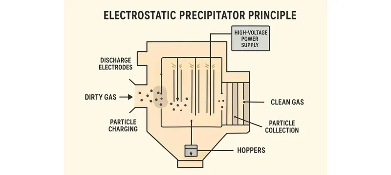
Corona discharge is the charging engine in active units. When the voltage between an ionising electrode and a nearby reference electrode exceeds a threshold, the local field ionises air molecules. The resulting ions collide with particles and transfer charge to them [1]. The threshold voltage depends on electrode geometry and is not a universal number.
The electrode arrangement varies by design. In many wire-plate precipitators, thin wires are held at high positive voltage and the collector plates are grounded. In some designs the plates alternate positive and ground; in others a different polarity scheme is used. The key point is that the electric field between the electrodes drives charged particles toward one set of surfaces.
Charged particles migrate toward the attracting plates under Coulomb force. Once they contact a plate, electrostatic image force and van der Waals attraction hold them. Collection efficiency therefore depends on the field strength, the particle's charge, the particle's aerodynamic size, and how long it spends in the field.
From air inlet to cleaned-air outlet
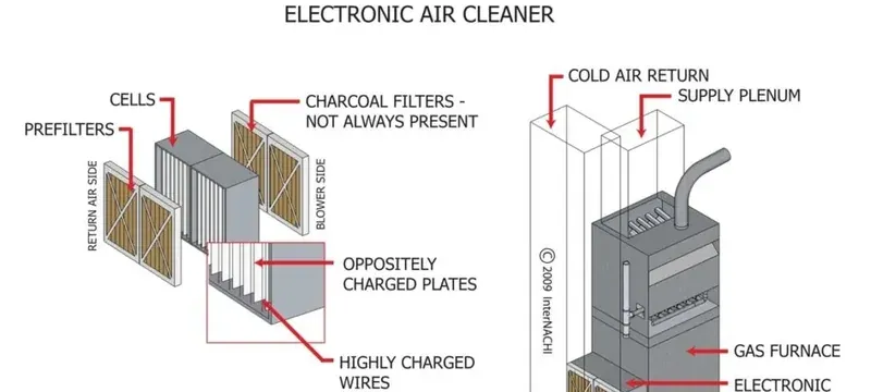
Air typically enters through a prefilter before reACHing the ionising section. The prefilter is common and often recommended because it captures lint, hair, and large debris that could bridge the ioniser electrodes and cause arcing. It is not universally required, and some compact designs omit it. Prefilter cleaning intervals depend on the manufacturer's instructions and the site's dust loading [2].
After the prefilter, air passes the ionising electrodes. Particles acquire charge, then enter the collector section. The charged particles deviate from the airflow streamlines and deposit on the collection plates, while cleaned air continues to the outlet. Bypass around the ioniser or collector reduces capture, so sealing matters.
How electrostatic air cleaners capture particles
How electrostatic air cleaners capture particles depends on whether the system is active or passive. Active electrostatic air cleaners charge particles with a powered corona and collect them on plates. That is the core answer to how electrostatic air cleaners capture particles, and it is the step that service work most often undoes. Passive electrostatic air cleaners rely on pre-charged media and mechanical interception.
The difference matters for selection. Active units offer controllable charging and washable collection cells but require electrical supply, interlocks, and periodic cell cleaning. Passive units are simpler to install and have no ozone concerns but cannot match the charging field strength of a powered precipitator.
Particle charging, migration, and collection efficiency
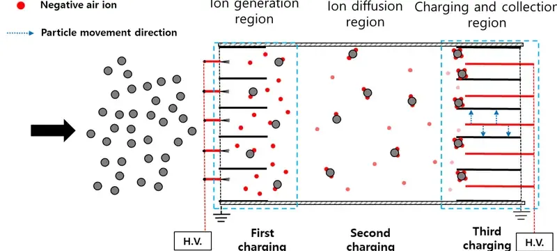
Field charging and diffusion charging overlap across particle sizes rather than switching at a fixed cutoff. Field charging dominates for larger particles, while diffusion charging is more significant for smaller ones, but the relative importance depends on particle diameter, ion concentration, residence time, and electrode geometry [1]. Statements such as "above 1 µm" or "below 0.2 µm" are illustrative rather than universal boundaries.
Once a particle carries charge, the electric field exerts a force proportional to its charge and the local field strength. The migration velocity increases with charge and field strength and decreases with aerodynamic drag. Collection occurs when the migrating particle reaches a plate and adheres.
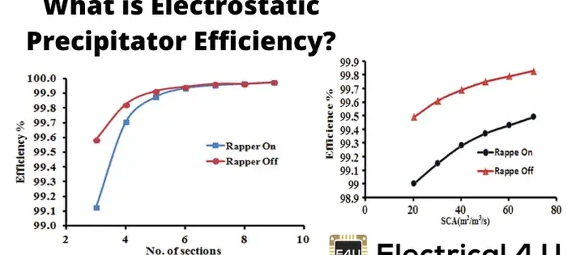
Efficiency is size-dependent. Published electrostatic precipitator studies report collection efficiencies in the 92–99.7% range for specific particle sizes, air velocities, and electrode configurations, but those figures are test-specific and should not be treated as general performance guarantees [2]. Any efficiency claim needs the test method, airflow, particle-size range, and product conditions.
Factors that change capture performance
Airflow rate affects capture through residence time. A simplified illustrative calculation: if a collector section has an internal volume of 0.02 m³ and the airflow is 2,500 m³/h, the nominal residence time is about 0.029 seconds. Halving airflow may increase residence time, but system airflow and operating conditions also change, so the relationship is not a simple doubling.
Plate loading changes performance. A thin, uniform dust layer has limited effect. A thick or uneven layer reduces the local electric field at the plate surface and can create arcing paths. Cleaning intervals are set by the manufacturer based on verified operating conditions and site dust loading.
Voltage affects charging intensity, but higher is not always better. Excessive voltage increases arcing risk and ozone generation. Corona discharge can generate ozone as a byproduct; arcing, contamination, and faults can increase emissions. California's CARB regulation sets an ozone emission concentration limit of 0.050 ppm (50 ppb) for certified indoor air cleaning devices sold in that state [3]. That is an emissions limit and certification test requirement, not a universal room-air concentration limit for all jurisdictions.
Electronic air filter designs and components
Active electronic air filter designs share a common architecture: an ionising section, a collector cell, a high-voltage power supply, and safety interlocks. The specific geometry, voltage, and control features vary significantly between models.
Deiiang™ product designer Jason.peng notes that one of the most common installation errors is insufficient service clearance around the cell. Design experience from commissioning shows that a cell needing 300 mm of removal travel cannot be serviced from a 200 mm gap, regardless of rated airflow.
Ionizer, collector cells, controls, and safety features
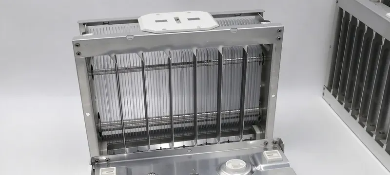
Ionising electrodes are commonly thin wires, but needle-point ionisers also exist. Collector plates are typically parallel metal plates spaced a few millimetres apart. Voltage, current, plate geometry, and safety controls are model-specific and should not be adjusted outside the manufacturer's procedures.
A model's output voltage, current setpoints, and plate spacing determine its charging and collection behaviour. The power supply converts mains voltage to the high DC voltage required. Interlocks cut power when the access panel opens. Some units provide alarm contacts for arcing or cleaning indication.
Washable cells and other electrostatic designs
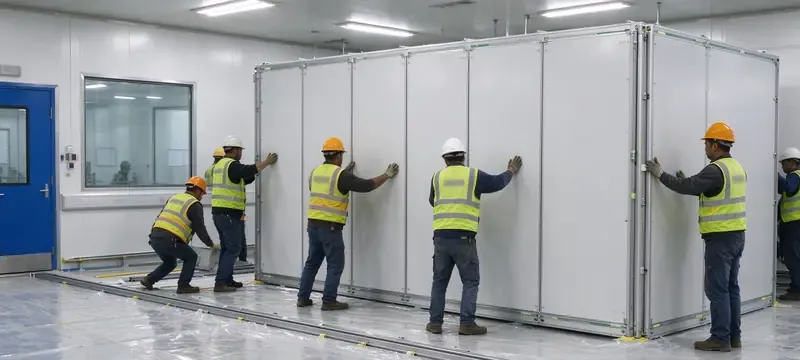
Active plate-cell designs often use washable cells, but dishwasher use is model-specific and must be confirmed from the product's cleaning instructions. Passive electrostatic designs use electret media and have no powered ioniser or collection cell. Hybrid systems combine a powered charging section with a media collector.
MERV applies to filter performance tested under ASHRAE 52.2, not as a generic conversion from a design type [4]. A passive electrostatic media product may have a MERV rating if it has been tested to that standard, but the rating should not be inferred from the technology alone.
Electronic air filter for HVAC applications
Integrating an electronic air filter for HVAC service requires matching airflow capacity to the system's design airflow, confirming that the fan can handle the filter's pressure drop, and providing service access for cleaning. Any electronic air filter for HVAC installation that skips one of those three checks tends to surface later as noise, nuisance arcing, or reduced airflow.
Table 1 lists illustrative airflow and pressure-drop ranges for common HVAC contexts. These are design examples, not validated limits for every installation. A hospital isolation room's ventilation and pressure relationships are room-design requirements, not filter specifications [5].
Table 1: Illustrative HVAC application parameters — design examples only, not universal sizing guidance.
| Application | Design airflow (m³/h) | Initial pressure drop (Pa) | Maintenance access | Control requirements | Example only or product-specific | Verification required |
|---|---|---|---|---|---|---|
| Commercial office AHU | 1,700–2,500 | 40–80 | Front or side slide-out cell | Basic on/off, airflow switch | Example only | Airflow and pressure drop at commissioning |
| Hospital isolation room | 1,000–1,900 | 50–90 | Front access door | Voltage adjust, alarm relay | Example only; room design governs | Room pressure and ventilation verification |
| Pharmaceutical packaging | 2,000–2,500 | 60–100 | Front access with clearance | BMS integration, ozone monitor | Example only | Product-specific data and ozone assessment |
| Cleanroom recirculation | 1,150–2,500 | 50–90 | Ceiling or side access | Interlock, differential pressure | Example only | Classification and filter scan evidence |
| Application | Design airflow (m³/h) | Initial pressure drop (Pa) |
|---|---|---|
| Commercial office AHU | 1,700–2,500 | 40–80 |
| Hospital isolation room | 1,000–1,900 | 50–90 |
| Pharmaceutical packaging | 2,000–2,500 | 60–100 |
| Cleanroom recirculation | 1,150–2,500 | 50–90 |
Sizing, installation, and system integration

Sizing begins with the system's design airflow. The filter's rated airflow must meet or exceed this value at the expected operating pressure drop. Undersizing forces higher face velocity, reducing residence time in the collector.
Bypass is a practical pitfall. A 5 mm gap around a 592 mm square cell creates roughly 0.012 m² of open area, about 3.4% of the 0.35 m² face area. Actual bypass depends on the gap geometry and sealing arrangement. Damaged or missing gaskets are common causes of reduced capture.
Deiiang™ catalogue data for pre-filters — which may precede electronic stages — provides reference points. A 592×592×381 mm six-bag medium-efficiency filter is rated at 2,050 m³/h with 3.18 m² media area and initial resistance below 100 Pa for F8 grade (catalogue data). These are companion products, not evidence of the electronic filter's capture efficiency.
Commissioning, controls, and performance verification
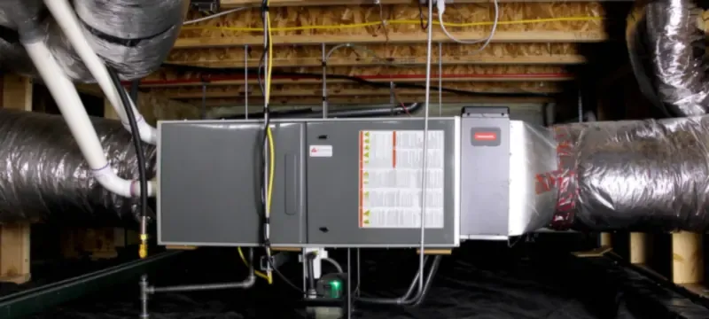
Commissioning verifies airflow, electrical operation, and alarm function. Baseline readings of pressure drop, airflow, and voltage provide the reference for future maintenance. A pressure-drop increase of 50% above baseline typically signals the need for cell inspection.
Ozone assessment may be required. Corona discharge can generate ozone, and arcing or contamination can increase emissions. The CARB certification test measures ozone emission concentration against the 0.050 ppm limit under specified conditions [3]. This is distinct from a room-air concentration requirement.
Deiiang™ provides verified catalogue specifications for its cleanroom filter range. HEPA classification is based on efficiency at the most penetrating particle size (MPPS), conventionally in the 0.1–0.2 µm range, not a universal 0.3 µm rating [6]. EN 1822-1:2019 classification values and product-specific test certificates should be consulted for actual performance.
Electronic air filters for cleanrooms
Electronic air filters for cleanrooms serve supporting roles — prefiltration ahead of HEPA stages and recirculation air cleaning — but they do not replace HEPA or ULPA final filters in classified cleanroom applications. They can reduce the particle load reaching downstream filters.
Deiiang™ (cleanroomequips.com) supplies cleanroom filtration products that are often used downstream of, or alongside, electronic prefiltration stages. These products are mechanical high-efficiency filters, not electronic air filters.
Suitable roles in cleanroom air systems
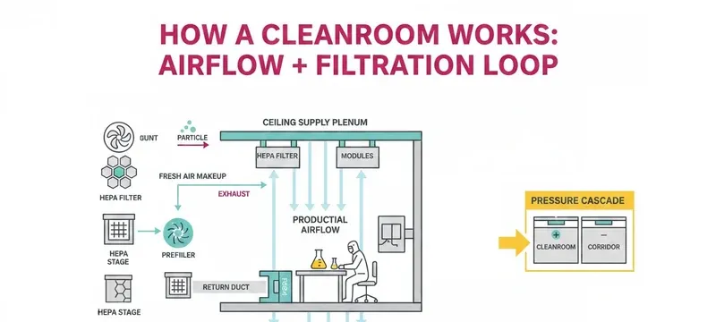
In a typical cleanroom air system, these electronic air filters for cleanrooms may serve as prefilters in makeup air units, as recirculation air cleaners, or as point-of-use devices for specific process areas. That is why electronic air filters for cleanrooms are usually judged on how much particle load they remove ahead of the HEPA stage rather than on a standalone efficiency claim. Prefiltration is the most common role.
Deiiang™ medium-efficiency pre-filters are classified under the legacy EN 779 system (F5–F9) as withdrawn categories. These should be identified as legacy classifications only; current general-ventilation classification uses ISO 16890 (ePM1, ePM2.5, ePM10) [7]. F5–F9 performance figures from catalogue data should not be presented as directly comparable to ISO 16890 results without the relevant test report.
The distinction between electronic filtration and HEPA filtration is fundamental. cleanroom design must meet its specified classification and validated performance, typically using appropriately selected final filters. Electronic filters provide upstream load reduction only.
cleanroom classification, testing, and project evidence
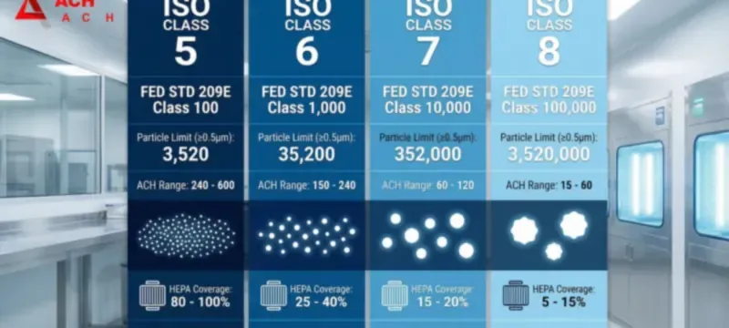
iso 14644-1:2015 defines the cleanroom classification system based on airborne particle concentration. iso 14644-3 specifies cleanroom test methods for classification and monitoring [8]. Filter classification and filter scan testing fall under different standards: ISO 29463-1:2024 (third edition) and EN 1822-1:2019 for high-efficiency filters, with ISO 29463-4 and EN 1822-4 covering the leak test method [6][9].
Table 2 separates cleanroom classification from individual filter scan testing. The evidence each produces is different: a particle-count report for the cleanroom, and a scan test report for the filter.
Table 2: Standards-to-test matrix — corrected test-method mapping.
| Activity | Applicable standard | Test method | Evidence produced |
|---|---|---|---|
| Cleanroom classification | ISO 14644-1 | ISO 14644-3 particle counting | Particle count report by location and size |
| HEPA/ULPA filter classification | ISO 29463-1 / EN 1822-1 | ISO 29463-4 / EN 1822-4 scan test | Filter scan test report with local penetration |
| General ventilation pre-filter | ISO 16890-1 | ISO 16890-2 / ISO 16890-3 | ePM1, ePM2.5, ePM10 efficiency and pressure drop |
| Individual filter leak test | ISO 29463-4 / EN 1822-4 | Scan test | Local penetration report for the filter |
| Activity | Applicable standard | Evidence produced |
|---|---|---|
| Cleanroom classification | ISO 14644-1 | Particle count report by location and size |
| HEPA/ULPA filter classification | ISO 29463-1 / EN 1822-1 | Filter scan test report with local penetration |
| General ventilation pre-filter | ISO 16890-1 | ePM1, ePM2.5, ePM10 efficiency and pressure drop |
| Individual filter leak test | ISO 29463-4 / EN 1822-4 | Local penetration report for the filter |
A pharmaceutical packaging cleanroom project illustrates the application. This is a company-reported case; independent verification records are not available for disclosure. Deiiang™ supplied low-profile H14 combined high-efficiency filters (592×592×292 mm, 2,500 m³/h, ≤220 Pa initial resistance, 20.04 m² media area) with F7 pre-filters and silicone-free gaskets. Per-unit DOP scan testing was performed.
Project-reported results described particle counts moving from an iso 7 baseline toward iso 6 conditions, with energy savings attributed to low initial pressure drop. Site location, project date, and specific measurement details are not disclosed.
Electronic vs mechanical air filters
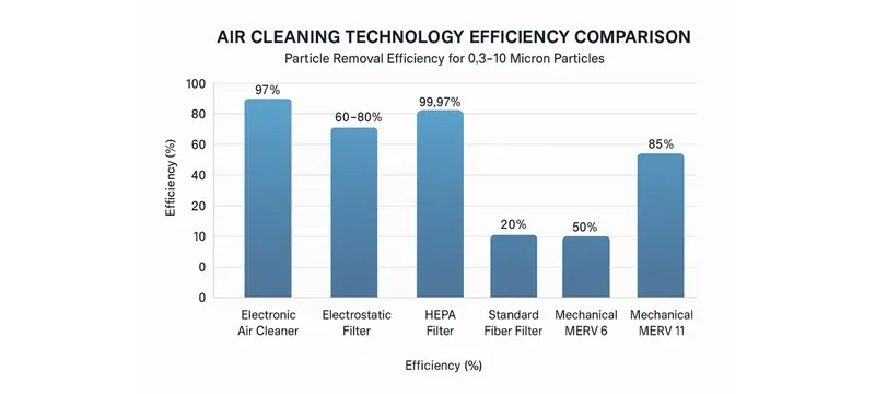
Electronic vs mechanical air filters is a comparison of operating principles, pressure-drop behaviour, maintenance mode, and efficiency evidence. Active electronic precipitators use electrostatic charging and low-pressure-drop collection cells. Mechanical filters use physical interception and impaction through fibrous media.
The trade-offs are real. Electronic units typically operate at lower pressure drop but require washing and produce less standardised efficiency data. Mechanical filters offer well-established ratings but consume more fan energy as they load.
Performance, energy, and maintenance trade-offs
Fan power for air movement can be estimated as: air power (kW) ≈ airflow (m³/s) × pressure drop (Pa) ÷ 1000 ÷ fan efficiency. At 2,500 m³/h (0.694 m³/s), 60 Pa, and 70% fan efficiency, air power is about 0.06 kW. At 150 Pa, the same calculation gives about 0.15 kW.
This estimate covers air power at a fixed operating point, before motor efficiency and control losses. The electronic unit's own electrical consumption must be added. A total energy comparison requires the same system operating point and includes both air-side and electrical-side power [10].
Maintenance shifts the cost structure. Washable cells require labour but no consumable media. Mechanical filters require periodic media replacement plus disposal. A lifecycle comparison should include energy, labour, media, and disposal costs.
Standards and evidence for fair comparisons
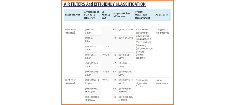
EN 1822-1:2019 classifies EPA, HEPA, and ULPA filters by efficiency at the MPPS. ISO 29463-1:2024 is the international equivalent, maintaining the same class structure [6][9]. The MPPS is typically in the 0.1–0.2 µm range, not a universal 0.3 µm value.
For general ventilation filters, ISO 16890 (ePM1, ePM2.5, ePM10) supersedes EN 779 [7]. ASHRAE 52.2 assigns MERV ratings based on particle size efficiency across three ranges: E1 (0.3–1.0 µm), E2 (1.0–3.0 µm), and E3 (3.0–10.0 µm) [4]. The current edition of ASHRAE 52.2 should be confirmed before citing a specific year.
IEST-RP-CC001 and MIL-STD-282 provide recommended practices and test methods for high-efficiency filters. Buyers should distinguish filter ratings from project acceptance criteria.
Electronic air filter maintenance and troubleshooting
Electronic air filter maintenance centres on cell cleaning, electrode inspection, and electrical safety verification. Neglecting maintenance reduces capture efficiency and may increase ozone generation.
Table 4 lists common symptoms and likely causes. It distinguishes symptoms from confirmed causes; a symptom alone does not confirm a fault. Safety-first guidance applies before any troubleshooting.
Table 4: Common symptoms, likely causes, and safe escalation.
| Symptom | Likely cause | Safe inspection | Escalation |
|---|---|---|---|
| Reduced efficiency | Dirty collection plates | Visual plate inspection after isolation | Clean per manufacturer instructions |
| Continuous arcing | Broken or contaminated electrode | Visual inspection after isolation | Qualified technician |
| Ozone odour | Arcing or contamination | Inspect electrodes after isolation | Investigate before resetting |
| Reduced airflow | Loaded prefilter | Check prefilter pressure drop | Clean or replace prefilter |
| Unit will not start | Interlock open or power fault | Verify door closed; check supply | Qualified technician |
| Repeated arcing after cleaning | Moisture or damage | Confirm fully dry; inspect plates | Qualified technician |
| Symptom | Likely cause | Escalation |
|---|---|---|
| Reduced efficiency | Dirty collection plates | Clean per manufacturer instructions |
| Continuous arcing | Broken or contaminated electrode | Qualified technician |
| Ozone odour | Arcing or contamination | Investigate before resetting |
| Reduced airflow | Loaded prefilter | Clean or replace prefilter |
| Unit will not start | Interlock open or power fault | Qualified technician |
| Repeated arcing after cleaning | Moisture or damage | Qualified technician |
Routine cleaning, inspection, and service intervals
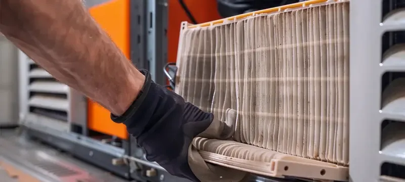
Cleaning intervals depend on the site's dust loading and the manufacturer's instructions. General guidance suggests monthly to quarterly in typical commercial service, but this is illustrative. The manufacturer's instructions specify the maximum loading condition.
Before any cleaning, follow the manufacturer's isolation and discharge procedure. Do not rely on the interlock alone to confirm de-energisation. Verify absence of hazardous voltage with appropriate equipment. Use qualified service personnel where required.
Cleaning methods, detergents, and dishwasher use are model-specific. Allow cells to dry completely before reinstallation. Inspect electrodes for damage during cleaning. Document the service date, cell condition, and any repairs.
Troubleshooting faults and safe return to service
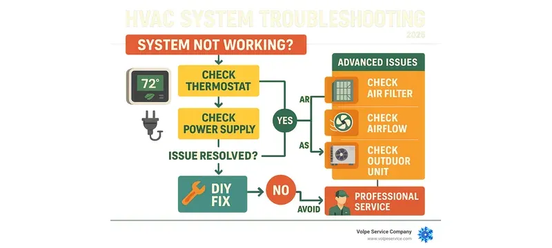
Electrical safety procedures are mandatory. Follow the manufacturer's isolation and discharge procedure. Verify absence of hazardous voltage with appropriate test equipment before touching any internal component. Voltage checks are not a general user task.
Airflow faults present as reduced system airflow or increased pressure drop. Check the prefilter first. If clean, measure pressure drop across the electronic cell per the manufacturer's procedure. Electrical faults present as alarms or loss of corona current; these require qualified diagnosis.
Persistent ozone odour after cleaning warrants investigation rather than repeated resetting. Disconnect power, inspect for contamination or damage, and verify operation only after the cause is identified. A qualified technician should diagnose and replace power supplies according to the manufacturer's procedure.
Selection, validation, and Deiiang project application
Selecting an electronic air filter requires matching airflow capacity and efficiency to the facility's requirements, confirming physical dimensions and control compatibility, and requesting verified test data.
Deiiang™ catalogue data provides verified specifications for cleanroom filter products. These are companion products to electronic filtration, not evidence of the electronic filter's capture efficiency.
Selecting a system against facility requirements
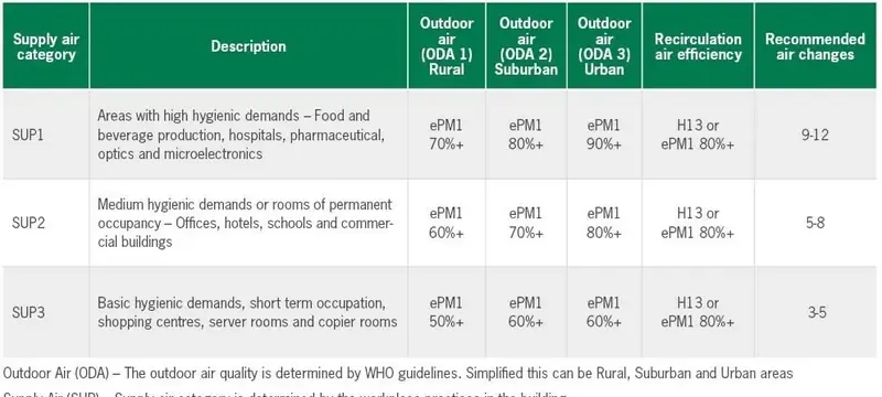
Selection starts with defining the contaminant: particle size range, concentration, and source. Airflow requirements determine physical size. Deiiang™ catalogue data for the 592×592×292 mm H14 filter shows 2,500 m³/h rated airflow with 20.04 m² media area (catalogue data; EN 1822 classification).
Physical constraints matter in retrofit projects. Limited plenum height may require low-profile designs such as the Deiiang™ DOP integrated filter, available in 120 mm and 150 mm depths (catalogue data). Control requirements range from simple on/off to BMS integration with alarm contacts.
Request verified test data for the specific product and application. Catalogue specifications are not a substitute for project acceptance testing.
Project case study and acceptance evidence
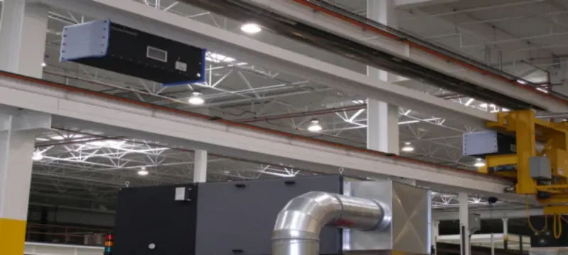
The pharmaceutical packaging cleanroom project is a company-reported case. The facility targeted iso class 6 with high ambient particle load and limited plenum height. Deiiang™ supplied H14 combined high-efficiency filters (592×592×292 mm, 2,500 m³/h, 20.04 m² media area, ≤220 Pa initial resistance — catalogue data) with F7 pre-filters and silicone-free gaskets.
Per-unit DOP scan testing was performed on every filter. Project-reported outcomes described particle counts moving from an ISO 7 baseline toward ISO 6 conditions, with energy savings attributed to low initial pressure drop. Site location, project date, sampling locations, baseline and final particle-count values, and the identity of the measuring party are not disclosed in available records.
Acceptance evidence for such projects typically includes filter test certificates, particle count reports, and documentation of airflow and pressure drop at commissioning.
Frequently Asked Questions
Do electronic air filters remove viruses?
Capture depends on the carrier particle, size, charge, airflow, and the tested unit. Electronic air filters may capture particles in viral size ranges, but capture does not establish inactivation or sterilisation. Claims of viral removal require validated test data under relevant conditions.
Do electronic air cleaners produce ozone?
Corona discharge can generate ozone as a byproduct. Arcing, contamination, and faults may increase emissions. California's CARB regulation sets an ozone emission concentration limit of 0.050 ppm for certified indoor air cleaning devices sold in that state [3]. Check applicable local requirements and product certification.
How often should an electronic air filter be cleaned?
Cleaning frequency depends on particle loading and the manufacturer's instructions. Typical commercial HVAC service intervals range from monthly to quarterly as illustrative guidance. Verify performance after cleaning by checking corona current and airflow per the manufacturer's procedure.
Can an electronic air filter replace a HEPA filter?
No. Electronic air filters capture particles with moderate efficiency and do not meet HEPA classification requirements. Cleanroom design must meet its specified classification and validated performance, typically using appropriately selected final filters. Electronic filters provide upstream load reduction.
Are electronic air filters more energy efficient than mechanical filters?
Electronic air filters may operate at lower pressure drop, which can reduce fan energy. However, the comparison must include the electronic unit's own electrical consumption, the same system operating point, and maintenance energy. A pressure-drop comparison alone does not establish total energy savings.
What standards should buyers check for electronic air filters?
Check ISO 16890 for general-ventilation efficiency ratings and ASHRAE 52.2 for MERV. For cleanroom applications, verify ISO 29463 / EN 1822 classification for any HEPA or ULPA filters in the system. Ozone certification may be required in some jurisdictions.
References
- [1] US 2018/0015482 A1, Electrostatic Air Filter Design and Assembly, United States Patent Application Publication.
- [2] Effects of high-voltage power sources on fine particle collection efficiency with an industrial electrostatic precipitator, ScienceDirect, 2012.
- [3] California Air Resources Board, Regulation for Limiting Ozone Emissions from Indoor Air Cleaning Devices, Cal. Code Regs. Tit. 17, § 94802.
- [4] ANSI/ASHRAE Standard 52.2, Method of Testing General Ventilation Air-Cleaning Devices for Removal Efficiency by Particle Size.
- [5] ANSI/ASHRAE Standard 170, Ventilation of Health Care Facilities.
- [6] EN 1822-1:2019, High efficiency air filters (EPA, HEPA and ULPA) — Part 1: Classification, performance testing, marking.
- [7] ISO 16890-1:2016, Air filters for general ventilation — Part 1: Technical specifications, requirements and classification system based upon particulate matter efficiency (ePM).
- [8] iso 14644-1:2015 and ISO 14644-3, Cleanrooms and associated controlled environments — Classification of air cleanliness by particle concentration; Test methods.
- [9] ISO 29463-1:2024, High efficiency filters and filter media for removing particles in air — Part 1: Classification, performance, testing and marking.
- [10] ASHRAE Handbook — HVAC Systems and Equipment, Fan energy and air power relationships.