+86 13638632902
 Jason@cleanroomequips.com


 MENU
MENU
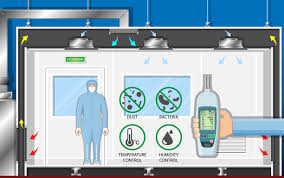
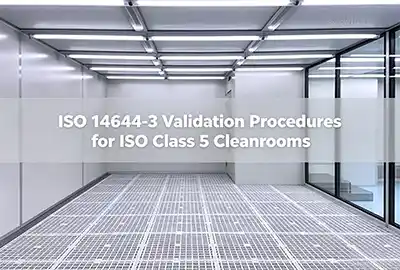
An ISO class 5 cleanroom requires more than a single particle-counting test to meet qualification standards. A robust cleanroom qualification procedure includes particle concentration, flow, and filter testing, along with pressure testing and monitoring the environmental parameters.
iso class 5 cleanrooms are utilized in sterile pharmaceutical manufacturing, aseptic filling and biologics production, electronic components manufacturing, assembly of devices, precision optics, microelectronics assembly, and semiconductor fabrication.
Particle counting is insufficient for cleanroom validation. Checking the HEPA filters is not the same as testing for particles in the cleanroom. Smart pictures are to be used as a study, not as a substitute. The occupancy state must be defined, and the calibration records must be appended to the test report.
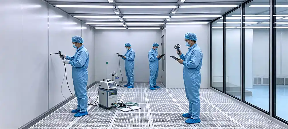
Common Validation Pitfalls: At-rest particle counts do not signify compliance on operational (dynamic) counts. Over 90% of turbulence of airflow is caused by the personnel in the room and the equipment's ability to cool itself. A dynamic smoke study is a requirement for iso 5 qualification.
This article explains how to create a cleanroom validation protocol, perform filter leak testing, conduct airflow visualization tests, and implement the ISO 5 certification steps, resulting in a properly qualified cleanroom.
iso 5 cleanroom Validation Summary
To clear ISO 5 Qualification, you must go through the stages written as
- Difficult tasks for your HVAC system Clarification
- The HEPA filter
- Documented qualification
- Concentration of particles
- Tested Pressure
- Patterns of airflow
ISO 14644 Standards Relevant to iso class 5 cleanroom Qualifications
To properly implement any cleanroom validation protocol, the family of ISO 14644 standards must be understood. Each of the documents serves a specific purpose.
ISO 14644-1 Air Cleanliness Classifications
ISO 14644-1 defines the classifications of air purity levels based on the concentrations of airborne particulates. ISO Class 5 represents one of the grades of air cleanliness. Various particle sizes channels have their own specified limits. The results should be evaluated in conjunction with the occupancy status and the number of samples drawn.
Acceptance shall be determined in accordance with the established protocols on the specified particle size channels, sampling point locations, and occupancy status contained in the approved documents.
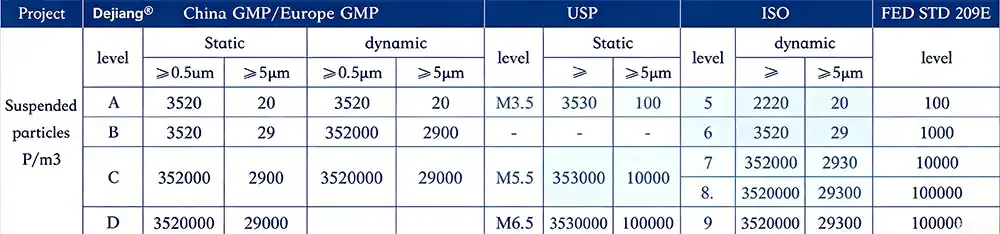
ISO 14644-1:2015 Particle Concentration Limits of ISO Class 5
| ISO Class | 0.1 μm (p/m³) | 0.2 μm (p/m³) | 0.3 μm (p/m³) | 0.5 μm (p/m³) | 1.0 μm (p/m³) | 5.0 μm (p/m³) |
|---|---|---|---|---|---|---|
| ISO Class 5 | 10,000 | 2,370 | 1,020 | 3,520 | 832 | N/A (ISO) / 29 (EU gmp grade a) |
*Note: The maximum allowable concentration for 0.5 μm and larger particulates is 3,520 particles/m³. ISO 14644-1 does not establish a limit for Class 5 for large particulates (5.0 μm and larger); however, EU GMP Grade A specifies 29 particles/m³ for 5.0 μm and larger of the same cleanness grade of cleanroom.
ISO 14644-2: Monitoring Plan
ISO 14644-2 outlines minimum requirements for a monitoring plan for the performance of a cleanroom. There is a difference between the initial qualification and the periodic monitoring. The frequency of monitoring shall be determined by the risk of the process and historical data. The primary factors are: particulate matter, differential pressure, temperature, humidity, and airflow.
The following intervals of re-qualification are established by ISO 14644-2:2015
- Airborne particles (ISO Class 5): maximum interval of 12 months.
- Airflow velocity and volume: maximum interval of 12 months (or after major changes).
- HEPA integrity filter leakage: maximum interval of 24 months (or after filter is replaced).
- Differentials in pressure, temperature, and humidity should be monitored continuously and reconfirmed at least once a year.
These are the maximum recommended time frames. Shorter time frames may be required by the results of an impact assessment, variations in regulations (i.e. EU GMP Annex 1), or client preferences.
iso 14644-3 — Methods of Testing
The ISO 14644-3 standard provides methods for testing related to the operation of cleanrooms. The standard encompasses determination of air velocity and air volume, air flow directions and visualizations, leaks in the filter systems, pressure differentials, temperature and humidity and their recovery, leaks in containment, and testing of airborne particulate concentrations.
GMP, FDA, and Other Requirements
- Pharmaceutical projects may also involve EU GMP Annex 1.
- Aseptic manufacturing involves a contamination control strategy.
- Semiconductor projects may focus on particles, airflow, pressure, and vibration.
- Medical device projects must align to client quality systems.
- ISO 14644 does not replace project URS, the Validation Master Plan, or the acceptance criteria of the client.
Figure 2: Relationships of ISO 14644 series — ISO 14644-1 (Classification) → ISO 14644-2 (Monitoring Plan) → ISO 14644-3 (Testing Methods) → Project URS / GMP / Client Acceptance Criteria.
[ Project Diagram: ISO 14644 Standards Relationship ]
ISO 5 Cleanroom Validation Protocol — Step-by-Step
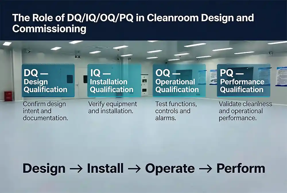
The cleanroom validation protocol describes a logical sequence of a process with many incremental steps.
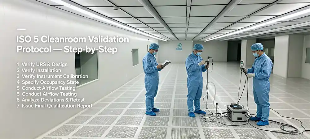
Step 1 — Verify the URS and Finalized Design
Before any form of testing is undertaken, it is important to determine: the function of the room, the area and height of the room, the number of personnel, the heat load of the equipment, the process contamination risk, the desired level of cleanliness, the pressure differential in the design, the temperature and humidity in the design, the occupancy, the instruments used, and what information is to be reported.
Fundamental principle: A validation test must affirm the approved intent of the design. It must not be used to address the lack of clarity of an incomplete design.
Step 2 - Verify Equipment Installation and Readiness
- Was the installation of the AHU completed?
- Were the ffus or terminal HEPA filters installed?
- Were HEPA filters installed and properly sealed?
- Was duct work and plenum sealing completed?
- Was room enclosure integrity completed?
- Are the doors and pass-throughs operational?
- Has the control system and sensors been calibrated?
- Are the filters stabilized before testing?
Step 3 - Verify Calibration of the Instrument
Any cleanroom validation protocol should include records of all instruments and their calibration. These records should include the instrument name, model, number, the date it was calibrated, the date that the calibration expires, the person who performed the calibration, the environment where the calibration was performed, the method used to calibrate, and the occupancy state of the room.
Step 4 - Specify the Occupancy State
The test results for the following three occupancy states can be quite different:
- As-built - The equipment is all installed but not powered on
- At-rest - Equipment is powered on and operating, but no personnel are in the room, nor is there any production activity
- Operational - The equipment, personnel, and production activity are all present
Critical: The occupancy state must be defined in the protocol and included in the final report. Results of different states should not be compared.
Step 5 - Conduct Airflow and Room Performance Testing
The ISO 5 certification steps require testing the volume and velocity of airflow as well as uniformity of airflow, testing the differential pressure of the room, visualizing airflow, leak tests on filters, measuring particle concentration, and measuring temperature and humidity as well as recovery time.
Step 6 - Analyze Deviations and Retest Until Passing
If a test fails, check in this order: the seal of the installed filter, the operating frequency of the fan, the pressure in the plenum, room enclosure integrity, gaps in the doors and pass-throughs, balance of airflow, the instruments used for the test, the technique of the test operator, and the state of the room occupant.
Step 7 — Issuing the Final Qualification Report
The qualification report includes identification of the project and room, purpose of the test, test standard, state of occupancy, instrument description, schematic of sampling points, raw data, calculation methods and evaluation, results, deviations, corrective measures, and final remarks, along with the signatures of the testing personnel and reviewer.
ISO Class 5 Cleanroom Filter Leakage Testing
Leak testing of cleanroom air filters is an integral part of cleanroom validation and is essential to validate that the HEPA filters and their respective installations are integral.
tOupc81Z0NM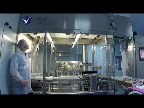
What Is A HEPA Filter Leakage Test?
The purpose of the test is to identify any localized damage to the filter media, to test the integrity of the filter to frame sealing, to verify the completeness of the installation interface, and to ensure that odorous air does not bypass the filter into the clean zone.
Filter leakage test (filter + installation seal) vs. particle count test (room air cleanliness) vs. airflow visualization test (flow and pattern of air).
Aerosol Selection and Concentration Control
The ISO 14644-3 and EU GMP Annex 1 standards allow for the use of polydisperse aerosol challenges, such as PAO (polyalphaolefin), DOP (dioctyl phthalate), and DEHS (diethylhexyl sebacate). Due to PAO's compatibility with photometers and its safety, it is the dominant aerosol.
Photometer Method (Mass Concentration)
- Determines total aerosol mass concentration
- Enables immediate detection of leaks with an alarm
- Leak threshold set to 0.01% of upstream concentration
- Useful for regular HEPA filter leak evaluations
- Concentration upstream: 10–20 μg/L (10–20 mg/m³)
DPC Method (Particle Counter)
- Counts individual particles at three sizes, 0.3, 0.5, and 5.0 μm
- More sensitive for ULPA filters
- Requires very low background particle concentration
- More time-consuming and data-intensive
- Best for semiconductor and very high precision work
Upstream Concentration Rule: There should be a concentration of 10–20 μg/L (10–20 mg/m³) of challenge aerosol upstream of the filter. Higher concentrations (exceeding 20 μg/L) may result in the formation of liquid droplets on the filter media which would shorten the life of the filter. In the case of gel-seal (liquid seal) filters, high pressure aerosol could destroy the gel and cause leak detection failures, which is a common problem.
Normal Filter Leak Testing Protocols
- Check that the necessary instrument calibrations are complete.
- Confirm the upstream aerosol concentration is sufficient.
- Calibrate the scanner and the photometer.
- Scan the filter face and frame, and the filter frame joints at a rate not exceeding 5 cm/s.
- Maintain the same scanning rate over the entirety of the frame.
- Corners, seal grooves, and interfaces can be prone to scanning blind spots. Pay special attention to these areas.
- Maintain an article record of where you found testing anomalies.
- Conduct testing at leak suspect locations.
- Change, repair, or recondition the filter.
- Conduct the reconditioning testing and complete the necessary records.
Frequent Areas of Fault and Failure
- Areas of damage to the HEPA media.
- Deformation of filter frames.
- Inadequate filter frame sealing.
- Filters not installed with the correct orientation.
- Plenum area sealing.
- Joints not fully sealed.
- Shipping and install damage.
Field Pitfall — PAO Residue & Gel Seal Failure: If the upstream PAO concentration is >20μg/L, PAO can load HEPA media rapidly and prematurely fail PAO media filters. For certain gel-seal filter frames, a PAO “high pressure” aerosol can gel leakseal “shock” the gel and cause a leak. A visual inspection of the gel seal is required prior to testing to ensure that the PAO levels are maintained between 10μg/L and 20μg/L.
Importance of HVAC Design Impact on Filter Leak Testing
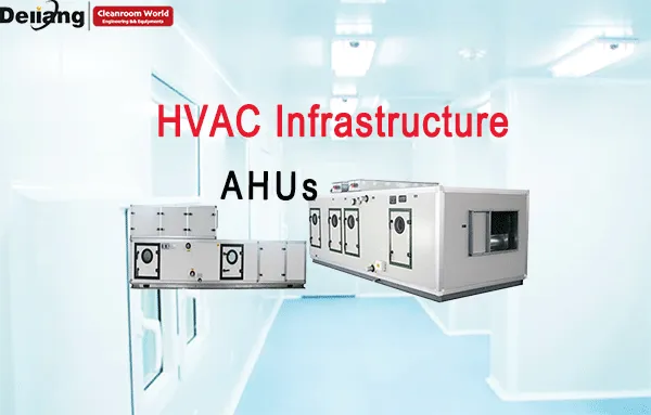
Deiiang™ systems offer stable supply air pressure that keeps testing conditions constant. An adjustable airflow range results in filter pressure from the air supply. Deiiang™ systems use variable frequency fans that minimize air pressure control fluctuations from the start-up and shutdown of the fans. A good unit air seal ensures that testing is done without additional pressure that causes system instability and leakage around it.
Figure 3: HEPA filter scan test schematic — upstream aerosol generator → HEPA filter → downstream clean zone → photometer → scan probe → filter frame → potential leak points.
[ Schematic: HEPA Scan Test ]
Testing Airflow in ISO 5 Cleanrooms
Airflow visualization testing is a method to qualitatively assess airflow direction, uniformity, and potential contamination.
The Aim of Airflow Visualization Testing
The aim of this test is to determine whether there is recirculation, vortex, short circuiting, and local stagnation in airflow within clean zones, as well as the potential carry of contaminants to those clean zones.
Testing Apparatus for the Airflow Smoke Study
- Choose testing locations.
- Choose locations for smoke release.
- Decide the most appropriate visualization medium.
- Record the room's state.
- Switch on and off the relevant apparatus as necessary.
- Capture the study on video.
- Make observations at positional locations within the process.
Critical Warning - Risk of Generating Smoke Study Residue: When testing in semiconductor wafer fabrication or in fiber optic assembly areas, dry thermal foggers can leave organic residues on sensitive surfaces. This can cause contamination of clean environments and loss of production. For these environments, use ultra-pure DI water fog or vapor in liquid nitrogen as the smoke study covers.
▶ Laminar Flow vs. Turbulence — GIF Animation
(replace with actual WebP/GIF showing unidirectional airflow vs. recirculation vortex)
(replace with actual WebP/GIF showing unidirectional airflow vs. recirculation vortex)
[Animated comparison]
Left: Stable unidirectional flow (In ISO 5 Zones), Right: recirculation, vortex, and short circuits.
Locations Requiring Testing
- Directly below HEPA supply terminals
- Directly above work surfaces
- Directly around open process equipment
- In the employee positions
- Directly at the cleanroom doors and pass-throughs
- Directly in front of return air grilles
- In the air gaps between process equipment and cleanroom walls
- In the product protection zone
What You Need to Know About Smoke Testing
desirable pattern: airflow is uninterrupted and inert, no airborne particulate flows into the protection zone, no vapor flow or stagnation, and inert smoke matches the test design and flows as intended.
To be investigated:
- upward roll-back of smoke
- persistent local vortex
- interference in airflow within adjacent areas
- backflow upon door opening
- changes in the movement of personnel that disrupt airflow in critical zones
- smoke stagnation behind equipment
Required Documentation
To capture abnormal airflow phenomena, documentation must include video and photos of the following parameters: the room number, the date of the test, the state of occupancy, the release point, the position of the camera, the test personnel, the conclusions of the tests, and any abnormal phenomena related to airflow.
Other ISO 5 Cleanroom Performance Tests
Airflow Velocity and Uniformity Test
When measuring airflow velocity on the supply side or in the working zone, sampling points will be determined based on room dimensions, the layout of terminals, and project protocols. Results will focus on averages, deviations, and anomalies that are specific to particular locations.
Industry Benchmark — Unidirectional Airflow Velocity
According to EU GMP Annex 1, unidirectional systems exhibit a consistent airflow of 0.36 to 0.54 m/s (70 to 100 fpm) at a height of 150 to 300 mm below the filter. ISO 5 semiconductor clean zones and ISO 5 pharmaceutical Grade A zones also fall within this range. Grade A zones, however, typically cite 0.45 m/s ± 0.1.
Critical Concept — ACH for Unidirectional Flow — A Common Pitfall
Many novice engineers try to determine air changes per Hour (ACH) for unidirectional ISO 5 zones. This is incorrect and is considered a beginner's mistake; unidirectional airflow systems for clean zones rely on piston-flow velocities of 0.36 to 0.54 m/s, while turbulent mixing and airflow are considered adequate for ISO 5 zones. Unidirectional flow and ACH are not related and will be incorrectly designed. ISO 5 Cleanroom systems are evaluated based on flow velocity, not ACH.
According to EU GMP Annex 1, unidirectional systems exhibit a consistent airflow of 0.36 to 0.54 m/s (70 to 100 fpm) at a height of 150 to 300 mm below the filter. ISO 5 semiconductor clean zones and ISO 5 pharmaceutical Grade A zones also fall within this range. Grade A zones, however, typically cite 0.45 m/s ± 0.1.
Critical Concept — ACH for Unidirectional Flow — A Common Pitfall
Many novice engineers try to determine air changes per Hour (ACH) for unidirectional ISO 5 zones. This is incorrect and is considered a beginner's mistake; unidirectional airflow systems for clean zones rely on piston-flow velocities of 0.36 to 0.54 m/s, while turbulent mixing and airflow are considered adequate for ISO 5 zones. Unidirectional flow and ACH are not related and will be incorrectly designed. ISO 5 Cleanroom systems are evaluated based on flow velocity, not ACH.
Room Pressure Differential Test
Measure pressure differentials for adjacent areas. Ensure that the direction of pressure adheres to the contamination control plan. Consider the door in both the closed and open positions. Determine the calibration of the pressure differential sensors. Analyze the pressure differentials considering the flow paths of personnel and materials.
Field Tip — Pressure Measurement Stability: At pressure differentials of 10–15 Pa for room measurement, a person walking outside the room or a duct for the HVAC can cause the sensor to drift by ± 3 Pa. When measuring room pressure differentials, using a 30-second averaging filter on the pressure transmitter will yield the most stable and repeatable value.
Airborne Particle Concentration Test
Choose an appropriate particle counter. Establish a plan for sampling locations. Order and document the sampling flow rate, sampling duration, and count the number of individuals present. Analyze the data in accordance with ISO 14644-1. Try to reduce the effects of personnel interaction and the start-stop behaviors of other equipment and other tests being performed.
ISO 14644-1 Sampling Point & Volume Calculator
Input the area of the clean room and select a flow rate of the particle counter in order to achieve an estimate of the total number of sampling locations necessary and the sampling time, which is recommended.
Sampling locations (NL): 10 points (√100 = 10.0 rounded up)
Minimum sample volume per location: 1000 L (1 m³) for ISO 5 at ≥0.5 μm
Recommended sampling time: ~36 min at 28.3 L/min
Minimum sample volume per location: 1000 L (1 m³) for ISO 5 at ≥0.5 μm
Recommended sampling time: ~36 min at 28.3 L/min
Formula: NL = √A (rounded up). Minimum volume = (20 / Cn,m) × 1000 liters. For ISO 5 at 0.5 μm, Cn,m = 3,520 particles/m³ → Vmin ≥ 5.68 L, but the practical minimum is 1 m³ per location.
Temperature and Relative Humidity Test
Temperature and humidity affect process stability, comfort of personnel, control of static electricity, moisture absorption of material, the operation of equipment, and the degree of risk of particles and microorganisms.
Recovery Time Test
Create a controlled particulate challenge. Record the time it takes to reach a specified level of cleanliness within the room. During this time, observe the supply air flow, the return air flow, and the condition of the filters. This test is applicable in situations requiring rapid recovery of the clean room.
100:1 Recovery Time — ISO 14644-3
The recovery test determines how fast a cleanroom reverts to the target cleanliness level post controlled aerosol challenge. The 100:1 Recovery Time is defined as the time the cleanroom takes to recover from an aerosol challenge 100 times the desired cleanliness level. For the majority of high-grade cleanrooms, a recovery time of 15 to 20 minutes is considered adequate. This test is applicable for cleanrooms with a non-unidirectional airflow system, and is best performed in the cleanroom's as-built or at-rest state.
The recovery test determines how fast a cleanroom reverts to the target cleanliness level post controlled aerosol challenge. The 100:1 Recovery Time is defined as the time the cleanroom takes to recover from an aerosol challenge 100 times the desired cleanliness level. For the majority of high-grade cleanrooms, a recovery time of 15 to 20 minutes is considered adequate. This test is applicable for cleanrooms with a non-unidirectional airflow system, and is best performed in the cleanroom's as-built or at-rest state.
Room Integrity and Leakage Assessment
Assess enclosure, door gaps, observation windows, pass-throughs, duct interfaces, plenums, and ceiling-to-wall connections.
How Deiiang HVAC Systems Support ISO 5 Validation
The Deiiang™ HVAC systems are equipped with features that support the cleanroom validation protocol and ongoing compliance.
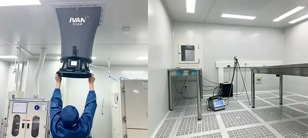
Stable Airflow Control
Variable frequency fans (20–120 Hz, depending on the model) are used for continuous airflow modulation. The static pressure controller is used to maintain the supply equilibrium. The multi-zone cooperative control functions for complex room arrangements. Stability in the supply air is achieved by the PID control. The traceability of the fans is achieved by the recorded operating data.
Field Practice – FFU Group Control & Auto-Resistance Compensation
The loading of HEPA filters increases the system resistance over time. As soon as the static pressure set point is reached, Deiiang™ controllers monitor the system pressure and increase the plenum fan's speed. This leads to a very accurate determination of the resistance at the filter (±2 Pa). This level of accuracy provides a significant advantage by eliminating the adjustment of the dampers, providing less maintenance, and significantly increasing the reliability of the system.
The loading of HEPA filters increases the system resistance over time. As soon as the static pressure set point is reached, Deiiang™ controllers monitor the system pressure and increase the plenum fan's speed. This leads to a very accurate determination of the resistance at the filter (±2 Pa). This level of accuracy provides a significant advantage by eliminating the adjustment of the dampers, providing less maintenance, and significantly increasing the reliability of the system.
Maintaining Control of Temperature and Humidity
The combination of a precise temperature and humidity sensor with a PID control loop offers the highest level of stability in temperature and humidity control. Cooling, heating, and humidification control adapts to seasonal variations. Control stability under load changes supports the validation of environmental parameter recordings.
Data Logging and Traceability
Automatic logging of operating parameters, such as the Supply/Return air temperature and pressure differential, records alarms and maintenance logs. The data is retained and exported to complete a documented audit trail for validation. The retention period is determined by the selected controller, storage architecture, and project configuration. For qualified projects, Deiiang™ offers contracts for data retention at requested locations.
Air Tightness and Maintainability
The sealed and insulated units contain integrated panels and doors to access Filters, an access ditch for condensate, Fan service access doors, a Sensor service access door, an access door for Internal Cleaning. These features provide long-term reliable performance.
Evidence that Needs To Be Provided
- Reports of product tests
- Reports of third-party tests
- Reports of project acceptance
- Data of airflow measurements
- Basis trend graphs for temperature and humidity
- Records from tests of filters
- Photos of installation of equipment
- Case studies with authorization
- Records of commissioning
Comparison Matrix — Conventional Fixed-Speed AHU vs. Variable-Speed Cleanroom AHU
✅ Variable-Speed Cleanroom AHU
- Airflow can be adjusted according to room load and pressure demand.
- Soft start and continuous modulation can reduce abrupt airflow changes.
- Operating parameters can be integrated into trend records.
- Can support different operating modes and commissioning conditions.
- May reduce energy consumption when the system is properly designed and controlled.
❌ Fixed-Speed AHU
- Airflow adjustment is relatively limited after installation.
- Frequent start-stop operation may cause pressure fluctuations.
- Manual balancing and recording may increase commissioning workload.
- Partial-load operation may be less flexible.
- Actual energy savings depend on design, control logic and operating schedule.
Comparison dimensions: airflow modulation, pressure control, partial-load operation, commissioning flexibility, data traceability, energy performance, maintenance complexity, initial investment, control system dependency, and application suitability.
Note: Energy performance depends on system design, operating schedule, fan selection, filter resistance, control strategy and actual room load.
Deiiang Case Study — ISO 5 semiconductor cleanroom Project
(Representative case study — client name anonymized per confidentiality requirements.)
Project Overview
- Industry: Semiconductor manufacturing
- Region: Southeast Asia (Malaysia)
- Clean area: Wafer fabrication and inspection
- Target: ISO Class 5
- Room count: 6
- Clean area: 1,200 m²
- Design state: Operational
- Main equipment: Deiiang™ variable-frequency AHUs, FFU system
- Project duration: 8 months
- Deiiang™ scope: AHU supply, installation supervision, commissioning support
Client Requirements
- Stable cleanliness
- Strict temperature/humidity control
- Continuous operation
- Low pressure differential fluctuations
- Support for quarterly and annual re-qualification
- Remote monitoring
- Easy maintenance
- Complete data records
Project Difficulties
- Seasonal load variation: Significant outdoor air condition differences between summer and winter affected cooling and dehumidification loads.
- Air balance across large clean areas: Airflow differences between multiple FFUs or terminals.
- Equipment heat and local thermal loads: Process equipment operation changed local temperature and airflow.
- Pressure differential fluctuations: Frequent door openings and material transfers affected adjacent room pressures.
- Validation data integrity: Without continuous equipment parameter recording, deviation investigation was difficult.
Localized Data — Southeast Asia High-Humidity Performance: In tropical climates (Malaysia/Vietnam semiconductor plants), dehumidification load accounts for over 40% of total HVAC energy consumption in ISO 5 cleanrooms. After integrating Deiiang™ variable-frequency systems, field measurements showed dew-point control accuracy of ±0.5°C and measured energy savings of approximately 18.5% compared to the previous fixed-speed installation.
Deiiang's Technical Solution
| Project Issue | Deiiang™ Solution | Evidence |
|---|---|---|
| Airflow fluctuation | Variable frequency fans + static pressure control | Fan frequency & static pressure trend chart |
| Multi-zone balance | Zoned control + on-site commissioning | Air balance report |
| Temperature/humidity variation | Coordinated temperature/humidity control | 24-hour trend chart |
| Data traceability | Control system with data logging | Data export screenshot |
| Maintenance difficulty | Modular access + filter maintenance design | Maintenance access photos |
Project Results
- Filter leak test: Passed / passed after corrective action
- Airflow visualization: Conforms to design flow / local optimization identified
- Pressure differential: Measured range within design limits
- Temperature: Measured range within design limits
- Relative humidity: Measured range within design limits
- Particle test: All size channels passed
- Recovery time: Measured value within specification
- Commissioning period: 14 days
Project-specific test values can be added after approval of the final validation report and client confidentiality requirements.
AHU installation
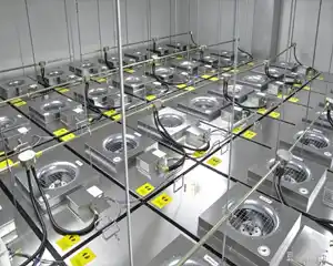
FFU / HEPA layout
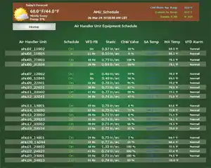
Control system trend data
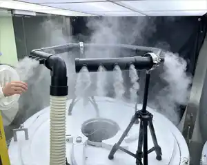
Smoke test in progress
Acceptance Criteria Summary Matrix — ISO Class 5 Cleanroom
| Parameter | Test Method | Acceptance Criterion | Reference |
|---|---|---|---|
| Particle concentration (≥0.5 μm) | ISO 14644-1 Annex A (Discrete-particle counter) | ≤ 3,520 particles/m³ (per location, average) | ISO 14644-1:2015, Table 1 |
| Particle concentration (≥5.0 μm) | ISO 14644-1 Annex A | N/A per ISO; ≤ 29 p/m³ (EU GMP Grade A) | EU GMP Annex 1 (2022) |
| Airflow velocity (unidirectional) | ISO 14644-3 Annex B (vane/thermo-anemometer) | 0.36 – 0.54 m/s (70–100 fpm), typical; based on design | EU GMP Annex 1 / iso 14644-4 |
| Airflow uniformity | Velocity mapping at ≥6 points per filter | ±20% of average (or as specified in protocol) | Project-specific |
| HEPA filter leak test | ISO 14644-3 Annex B.6 (Photometer scan) | No leak > 0.01% upstream concentration | iso 14644-3:2019 |
| Room pressure differential | ISO 14644-3 Annex B.5 (Manometer / transducer) | ≥ 10 Pa (or as designed) relative to adjacent spaces | ISO 14644-4 / GMP |
| Temperature | ISO 14644-3 Annex B.7 (Calibrated sensor) | Design setpoint ± tolerance (e.g., 21 ± 1°C) | Project-specific |
| Relative humidity | ISO 14644-3 Annex B.7 (Calibrated sensor) | Design setpoint ± tolerance (e.g., 45 ± 5%) | Project-specific |
| Recovery time (if applicable) | ISO 14644-3 Annex B.13 (100:1 challenge) | Typically ≤ 20 minutes to baseline | Project-specific / ISO 14644-3 |
ISO 5 Cleanroom Validation Checklist
Progress: 0 / 12 completed
Should You Use a Central AHU, FFU System or a Hybrid Configuration?
✅ Advantages of a Central AHU
- Centralized temperature and humidity control.
- Suitable for large cleanroom areas.
- Centralized filtration and maintenance planning.
- Convenient integration with building management systems.
❌ Potential Limitations
- Higher impact if the central unit stops.
- Requires careful duct and pressure design.
- Commissioning can be more complex in multi-zone systems.
- Long duct routes may increase pressure loss.
System options to consider: Central AHU, FFU-only system, AHU + FFU hybrid, constant-volume system, variable-air-volume system. No single system fits every ISO 5 project. Selection depends on room area, process heat load, operating schedule, temperature/humidity requirements, process equipment layout, maintenance conditions, initial investment, energy costs, and future expansion needs.
FAQ — ISO 5 Cleanroom Validation
Q1
Is ISO 14644-3 a certification standard?
ISO 14644-3 specifies test methods. ISO 14644-1 is used for cleanliness classification. Project acceptance combines design, test results and client requirements. It is not simply called "ISO official certification."
Q2
What tests are required for an ISO Class 5 cleanroom?
Particle concentration testing, airflow testing, HEPA filter leak testing, pressure differential testing, airflow visualization, temperature/humidity, and recovery time and room integrity testing as required by the project.
Q3
How often should HEPA filter leak testing be performed?
Frequency depends on risk assessment, industry regulations, client requirements and monitoring trends. Re-testing is typically required after initial qualification, major maintenance, filter replacement or abnormal events. A single universal interval is not sufficient.
Q4
What is the difference between a smoke test and an airflow test?
Airflow velocity testing provides quantitative data. Smoke testing provides visual evidence of flow pattern and direction. They cannot replace each other.
Q5
Can an ISO 5 cleanroom pass particle testing but fail airflow visualization?
Yes. The room may temporarily meet particle concentration requirements but have recirculation, short-circuiting or inadequate protection of critical zones. Particle testing and airflow visualization should be analyzed together.
Q6
How can HVAC design improve ISO 5 qualification?
By maintaining stable airflow and static pressure, reducing temperature/humidity fluctuations, supporting multi-zone control, providing traceable operating data, and facilitating filter maintenance and system commissioning.
Q7
What should be included in a cleanroom validation report?
Test protocol, occupancy state, sampling point layout, instrument calibration, raw data, calculation methods, deviations, corrective actions, re-test results, and final conclusion.
References
- ISO 14644-1:2015 — Cleanrooms and associated controlled environments — Part 1: Classification of air cleanliness by particle concentration
- ISO 14644-2:2015 — Cleanrooms and associated controlled environments — Part 2: Monitoring to provide evidence of cleanroom performance related to air cleanliness by particle concentration
- ISO 14644-3:2019 — Cleanrooms and associated controlled environments — Part 3: Test methods
- EU GMP Annex 1 (2022) — Manufacture of Sterile Medicinal Products
- IEST-RP-CC034.2 — HEPA and ULPA Filter Leak Test
Product design by Jason.peng · Deiiang™