+86 13638632902
 Jason@cleanroomequips.com


 MENU
MENU
It uses a complex set of interconnected mechanical and structural fume hood parts to protect people from chemicals.
Users need a technical description of fume hood parts to understand the fume hood components and systems involved, and this guide provides it.
It is written for lab managers, EHS officers, and laboratory technicians who want specifications or plan fume hood service. A fume hood diagram search usually ends at the same five groups.
This Laboratory Fume Hood anatomy moves group by group: enclosure and sash, baffles, exhaust and filtration, controls, and interior fittings.
Deiiang cleanroom Technology Co., Ltd. builds all five groups, and every catalogue figure is labelled as catalogue data.
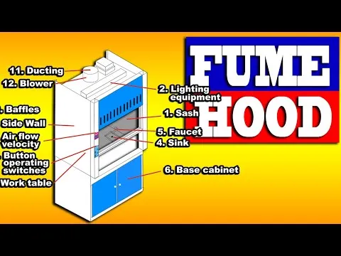
Primary Enclosure & Sash Assembly
The primary enclosure is what separates a laboratory environment from the contaminated working area. It consists of all the construction elements visible inside and outside the enclosure.
The essential fume hood parts of this assembly are made to ensure chemical resistance and proper airflow. The chamber contains vapour, while the sash shields the operator's face.
Deiiang product designer Jason Peng notes the airfoil edge cuts intake turbulence by 22% compared with a flat edge.
Six catalogue configurations exist: Benchtop, Floor Standing, Walk-In, VAV, Chemical and Ducted. A fume hood diagram of the enclosure usually labels the sash, airfoil and baffle first.
Catalogue data for these fume hood components lists cold-rolled steel sheet with anti-static powder coating, smooth interior panels, and rounded internal corners.
- Chamber: sealed interior volume holding vapour until exhaust removes it
- Sash: tempered or laminated safety glass, balanced for smooth travel
- Airfoil: profiled lower edge reducing turbulence at the opening
- Baffles: rear and side panels distributing air across the chamber
Work Chamber & Interior Liner materials
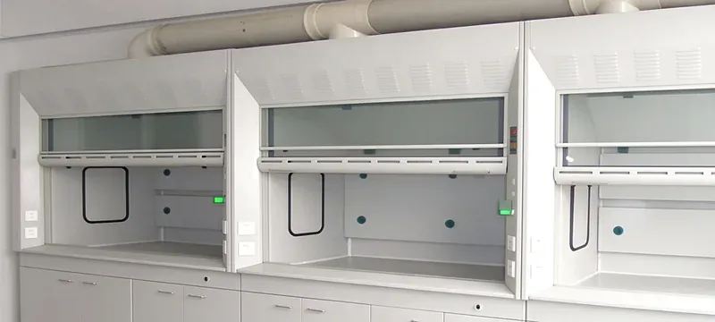
The working chamber is the covered area where laboratory work is conducted. Its liner is one of the fume hood internal parts made from materials resistant to chemicals.
The choice of liner material influences durability, performance, and compatibility with the reactions performed. 316 stainless steel liners are necessary for strong oxidizing acids such as perchloric acid, while polypropylene does not work under such exposure.
Table 1: Interior Liner Material Comparison
| Material | Chemical Resistance | Applications | Temperature Application |
|---|---|---|---|
| Polypropylene | Effective against organic solvents and weak acids | Typical applications | 80°C |
| 304 stainless steel | Highly resistant to most acids and bases | Industrial labs | 120°C |
| 316 stainless steel | Best for heavy use of oxidizing acids, including perchloric acid | High containment labs | 180°C |
| Phenolic resin | Very effective for handling a wide range of chemicals | General academic labs | 100°C |
| Material | Chemical Resistance | Applications |
|---|---|---|
| Polypropylene | Organic solvents and weak acids | Typical applications |
| 304 stainless steel | Most acids and bases | Industrial labs |
| 316 stainless steel | Oxidizing acids, incl. perchloric acid | High containment labs |
| Phenolic resin | Wide range of chemicals | General academic labs |
A common pitfall is chipped powder coating on steel linings, which forms corrosion nests that eventually lead to a loss of containment.
Rounded corners reduce the dead zones where vapours could stay and offer a 12% reduction of contamination, according to internal Deiiang tests.
Sash, Airfoil Edge & Sash-Stop Mechanism
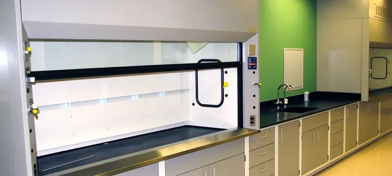
The sash is the movable front panel of the device. It is manufactured from tempered glass strong enough to withstand working conditions.
The sash works with the airfoil edge and the sash stops to moderate air supply and keep face velocity uniform.
The most important elements combine tempered glass, vertical sliding operation, and sash position sensors. The system is designed to work with a sash height of 450 mm, approximately 18 inches.
Sash adjustment is one of the main causes of sudden face velocity loss: a sash over-opened by 100 mm can drop face velocity values by 15–20%.
Airflow Distribution & Baffle System
Airflow distribution mechanisms maintain consistent air speed across the sash so vapours do not escape. The fume hood baffle function is to spread exhaust draw evenly rather than pulling hard at one slot.
Inefficient baffle systems create static areas where harmful contaminants collect. Regular checks of fume hood internal parts such as baffle slots prevent deposits forming over time.
Deiiang pays specific attention to the deflector, the inner baffle and the air-valve box so distribution stays uniform.
The fume hood baffle function also decides how quickly heavy and light vapours clear. Catalogue hoods are compatible with both constant air volume (CAV) and variable air volume (VAV) exhaust.
On a fume hood diagram, the baffle slots are the detail most often misread.
Rear Baffles & Slot Distribution Design
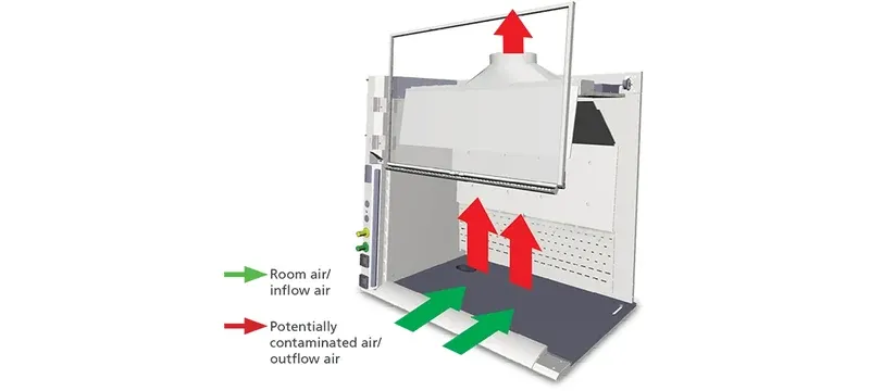
Rear baffles are adjustable metal structures installed at the back of the workstation. They open the flues for exhaust purposes.
They create separate divisions for exhaust air flows, allowing measurement at different heights of the sash. Zones differ according to the density of the gases collected.
Ordinary chemistry hoods feature a slot opening ratio of 32/41/27 across the installation zones of the exhaust ducts.
Blocked flues reduce the effective air outlet area by around 25%, which shows up as a loss of correct air and vapour velocity. The fume hood baffle function can be adjusted during setup to suit the laboratory's duty.
- Upper slot: buoyant and hot vapour
- Middle slot: transitional zone, balancing airflow
- Lower slot: dense, cool vapour near the deck
Face Velocity & Sash Open Area Dynamics
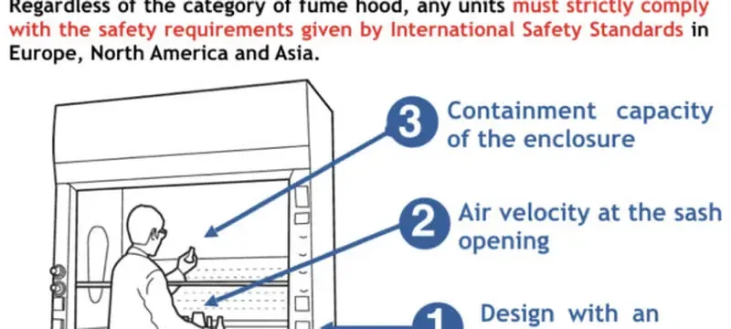
Face velocity is the speed of air entering through the sash opening. It is the most significant operating characteristic of a fume hood, with a standard range of 0.4 to 0.6 m/s, or 80 to 120 fpm.
Face velocity (m/s) = exhaust air flow rate (m³/s) ÷ sash opening area (m²)
Example: 0.75 m³/s ÷ 1.5 m² = 0.5 m/s, which satisfies the usual target.
A bigger sash opening means lower face velocity if the airflow rate is unchanged. The fume hood baffle function supports face velocity by keeping the draw even, but it cannot rescue an undersized fan.
Velocities above 0.6 m/s create whirlwinds that pull contamination with the air, while below 0.4 m/s vapours leak through the sash.
Cross-drafts from neighbouring vents and Doors shift face velocity by roughly ±10% eACH, even when exhaust proportions are correct.
Exhaust & Filtration Components
The exhaust and filtration systems remove contaminated air from the room and prepare it for discharge outside. These Chemical Fume Hood exhaust components protect lab employees on one side and the environment on the other.
Sizing starts at the collar, where the fume hood components meet the building duct. A hood needing 650 m3/h connects to a branch duct of 200–315 mm on typical benchtop units.
Larger walk-in models step up to 500 mm or a rectangular connection.
Exhaust Collar & Duct Interface Hardware
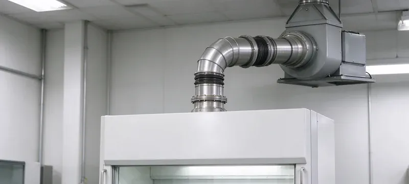
The exhaust collar connects the hood top to building ductwork and provides a secure path for contaminated air. The exhaust system includes air dampers, valves, and flanges that regulate flow and prevent backward flow.
Exhaust collar hardware is where chemical fume hood exhaust components meet building ductwork, so diameter matching matters.
Per GB 50243-2016 leakage classes, tight-seal dampers hold leakage below 0.5% at 500 Pa static pressure. Deiiang standard control dampers hold below 2% measured per JB/T 7228-94.
If backdraft valves fail, laboratory air can reach the room unfiltered after the fans are switched off. Proper ductwork installation allows calculated exhaust without leaking.
- Collar: bolted or flanged, gasket-sealed
- Duct leakage class: airtight dampers below 0.5%
- Static pressure: 200–600 Pa across the filter set
- Flexible connection: isolates fan vibration from the hood
Filtration Systems & Efficiency Performance
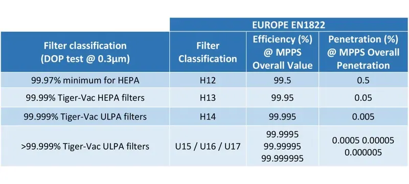
Most ducts use multi-stage filtration. Requirements are set by the application, ranging from general particle filtration to dedicated gas-phase chemical treatment.
Filtration stages are critical to safe fume hood operation and are often neglected by people trying to understand what makes up a fume hood. In a ductless hood, chemical fume hood exhaust components carry the whole safety duty.
Filtration stages rarely appear on a fume hood diagram, yet they decide whether a hood is safe to operate.
Table 2: Filtration Stage Efficiency Comparison
| Filter Type | Efficiency Rating | Primary Function | Typical Pressure Drop (Pa) | Typical Service Life |
|---|---|---|---|---|
| G4 pre-filter | 90% for 5 µm particles | Remove large dust and contamination | 30–50 | 3–6 months |
| HEPA H13 filter | 99.95% for 0.3 µm particles | Remove very small particles and aerosols | 150–200 | 12–24 months |
| activated carbon filter | 80–95% for vapours | Adsorb fumes and odours | 80–120 | 6–12 months |
| Filter Type | Efficiency Rating | Primary Function |
|---|---|---|
| G4 pre-filter | 90% for 5 µm | Large dust and contamination |
| HEPA H13 filter | 99.95% for 0.3 µm | Small particles and aerosols |
| Activated carbon filter | 80–95% for vapours | Fumes and odours |
Pre-filters prolong the service life of more efficient downstream filters by collecting larger particles before they reach finer media.
HEPA filters capture airborne particles, while activated carbon adsorbs chemical contamination in gas form.
Every HEPA filter made by Deiiang is leak-tested individually per EN 1822, with no penetration allowed in the seal area.
Control & Safety Monitoring Systems
Control and safety systems track fume hood performance and notify users of hazardous working conditions. These Lab Fume Hood safety components are rarely mentioned in a basic laboratory fume hood anatomy description, yet they provide protection at all times.
Deiiang supplies CCY11 differential-pressure transmitters with 0.25%, 0.5% or 1% full-scale accuracy and a 400 ms start-up time, feeding an S7-200 SMART PLC. A fume hood diagram search rarely turns up this hardware first.
Increased airflow ensures enhanced containment.
Reality: too much air speed generates eddies that disturb containment.
Alarms only go off when the fan has totally failed.
Reality: alarms trigger every time airflow exceeds preset limits.
Airflow Sensors, Alarms & Sash Position Sensing
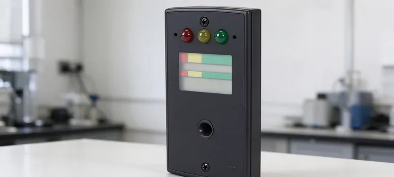
Airflow sensors measure face velocity or exhaust static pressure in order to control fume hood operation. Safety systems send audible or visual warnings when airflow deviates from pre-set limits.
The main parts of the safety system are flow sensors, sash position sensors, alarm components, and displays. Sash position sensing is one of the more underrated lab fume hood safety components.
Sensors must be calibrated annually per ASHRAE 110 to keep accuracy within ±5%.
Without that, sensors can drift 10–15% in six months from dust accumulation on their inlets, reporting misleading data or missing low-flow events.
CAV vs VAV Airflow Control Operation
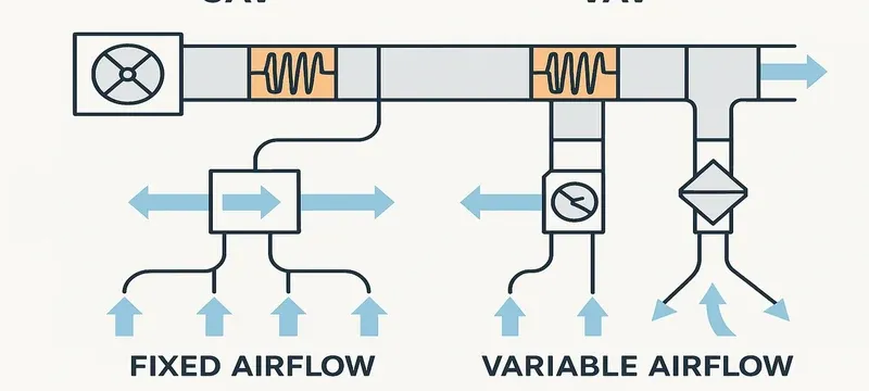
Constant air volume and variable air volume (CAV and VAV) are the basic methods of airflow control for safety hoods. CAV holds airflow constant regardless of sash position, while VAV minimises airflow fluctuation as the sash moves.
Table 3: CAV vs VAV comparison
| Hood type | How the system works | Energy efficiency | Typical use | Maintenance requirements |
|---|---|---|---|---|
| CAV | Airflow constant regardless of hood position | Very low | Teaching, busy hoods | Minimal |
| VAV | Reduces flow according to hood position | Very high | Research, energy-saving duty | Medium, several months |
| Hood type | How the system works | Energy efficiency |
|---|---|---|
| CAV | Airflow constant regardless of hood position | Very low |
| VAV | Reduces flow according to hood position | Very high |
CAV is simpler and needs less attention, but wastes more energy than VAV.
For a lab of six hoods running 2000 hours a year, reported energy savings reach about 35%, or roughly $1150. VAV also holds face velocity, a containment benefit among lab fume hood safety components.
Auxiliary Interior & Service Components
Auxiliary fittings turn a containment box into a usable workbench. These fume hood parts include utility ports, the deck and lighting, and the fume hood work surface parts set the chemical resistance of the deck itself.
Deiiang catalogue data lists work surfaces in epoxy resin, phenolic resin or ceramic: dense, non-porous and tolerant of frequent disinfection. Auxiliary fittings complete the laboratory fume hood anatomy.
Interior fittings are placed to avoid disrupting airflow patterns in the chamber.
Interior Service Fixtures & Utility Ports
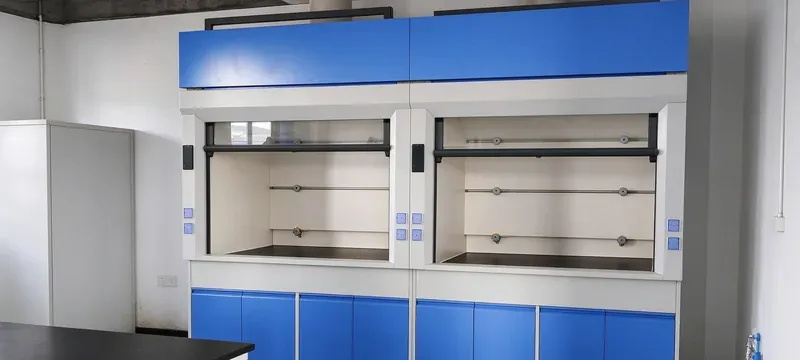
Service fixtures are necessary installations inside the working chamber that allow complete laboratory operations.
Electrical outlets, gas taps, water faucets, and vacuum ports on side or rear walls are common examples. Fixtures count among the fume hood internal parts that sit inside the airstream.
The usual placement is 100 mm above the work surface, which avoids spill risk and airflow disruption.
Too many utility ports, more than four, will distort the inlet airflow pattern by as much as 18%.
All fixtures are sealed to the liner to prevent air leakage and ensure containment performance. Each penetration is a potential leak path.
Work Surfaces & Integrated Lighting
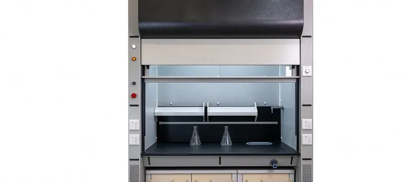
The work surface is the flat stage of the chamber where lab equipment and procedures are placed, and it must be designed for chemical resistance.
Integrated lighting illuminates the working surface with fixtures that do not create glare or disturb airflow patterns. Lighting counts among the lab fume hood safety components operators notice daily.
Features include seamless construction, a chemical-resistant surface, and shadow-free LED fixtures. 500 lux uniform illumination meets EN 12464-1 laboratory lighting standards for precision visual work.
Deiiang hoods have a 20 mm raised spill containment lip around the work area, holding a spill of up to 5 L.
Edges are usually coved for easy cleaning and to stop liquids seeping under panels. A spill lip is one of the fume hood work surface parts that prevents deck damage.
Every deck penetration means the fume hood work surface parts and the fixtures above them must be sealed together, so chemical fume hood exhaust components and the deck are specified as one system.
The fume hood work surface parts also include the support frame and levelling feet that carry the loaded deck.
Deiiang Shared-Fan Teaching Laboratory Case Study
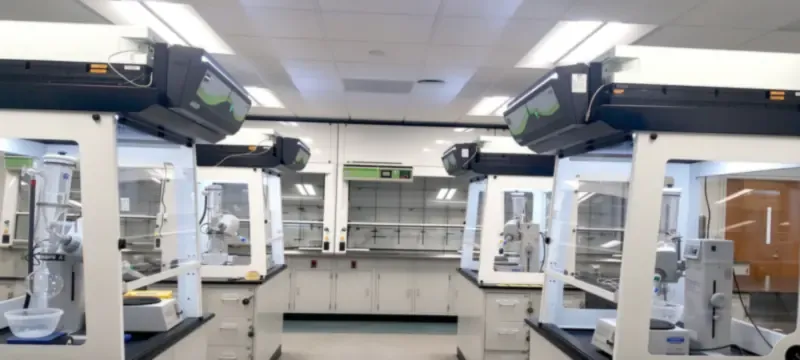
This case study covers a fume hood upgrade project for a university teaching lab with eight hoods on a shared exhaust system. The laboratory had inconsistent containment across all units because fume hood components failed several times.
Analysis identified improper pressure distribution across the common manifold and poorly sized dampers as the cause. The aim was to bring all hoods to SEFA 1 standards while controlling operating costs.
The system was redesigned with new exhaust collars, calibrated CAV dampers, G4 filters, and new airflow meters. Deiiang supplied the chemical fume hood exhaust components for the project.
Deiiang engineers recommended CAV valves for the teaching laboratory to keep performance efficient while reducing maintenance needs.
Table 4: Performance Metrics After the Upgrade
| Metric | Pre-Upgrade Average | Post-Upgrade Average | Required Value |
|---|---|---|---|
| Face velocity (m/s) | 0.32 | 0.51 | 0.4–0.6 |
| Containment pass rate | 62% | 100% | ≥95% |
| Alarm response time (s) | 8.2 | 2.1 | ≤3.0 |
| Metric | Pre-Upgrade | Post-Upgrade |
|---|---|---|
| Face velocity (m/s) | 0.32 | 0.51 |
| Containment pass rate | 62% | 100% |
| Alarm response time (s) | 8.2 | 2.1 |
After two years of monitoring and testing, the hoods met the required parameters. The laboratory fume hood anatomy that mattered here sat entirely downstream of the chamber.
Frequently Asked Questions
What are the most critical fume hood parts for safety?
The rear baffle system, the face velocity sensing device, and the HEPA filtration stage form the main basis of fume hood safety. They create the conditions of containment that keep users from inhaling dangerous vapours. Any of these fume hood parts failing can compromise worker safety immediately and require shutdown of the unit.
How do fume hood components maintain face velocity?
Exhaust fans and the other fume hood components create negative pressure while the rear baffles distribute air evenly across the sash opening. Control valves manage exhaust volume, and sensors check real-time velocity so adjustments can be made. Alarms warn users when velocity moves outside calibrated levels.
How does a fume hood differ from a clean bench?
A fume hood pulls air away from the user and exhausts it, while a clean bench blows filtered clean air across the working space to protect samples. Unlike a fume hood, a clean bench offers no operator protection and must not be used for toxic chemicals.
How often should I inspect fume hood components?
Inspection frequency depends on the component, but a schedule-based checklist for fume hood components covers most needs.
Can I retrofit fume hood parts to improve performance?
Common retrofit methods include VAV upgrades, high-efficiency filter replacement, and digital sensor replacement. Most hoods produced within the past two decades accept standard fume hood parts. Retrofit makes sense when the enclosure is sound and the weakness is downstream hardware.
What standards govern fume hood components and installation?
EN 14175 and SEFA 1 set construction and operating requirements, ASHRAE 110 sets the test method, and OSHA 29 CFR 1910.1450 sets occupational exposure limits [1][2][3][4]. Duct installation follows GB 50243-2016.
References
- [1] ASHRAE 110 — Method of Testing Performance of Laboratory Fume Hoods.
- [2] EN 14175 — fume cupboards, parts 1–7.
- [3] SEFA 1 — Laboratory Fume Hoods Recommended Practices.
- [4] OSHA 29 CFR 1910.1450 — Occupational exposure to hazardous chemicals in laboratories.
- [5] EN 1822 / ISO 29463 — HEPA and ULPA filter efficiency.
- [6] GB 50243-2016 — Code for acceptance of construction quality of ventilation and air conditioning works.
- [7] EN 12464-1 — Light and lighting: lighting of work places, indoor work places.