+86 13638632902
 Jason@cleanroomequips.com


 MENU
MENU
A damper is defined as a movable plate situated inside ductwork that controls airflow. It is the main devICe in HVAC systems used for balancing air or isolating it.
So what is a damper? It is an adjustable obstruction that modifies a free area for air to move.
What is an HVAC damper? It is the same thing but used in airside duties instead of a water or steam side duty. In this article, we will explain the damper definition, types, choice, commissioning, and problems.
Also, we will explain how the damper operates daily.
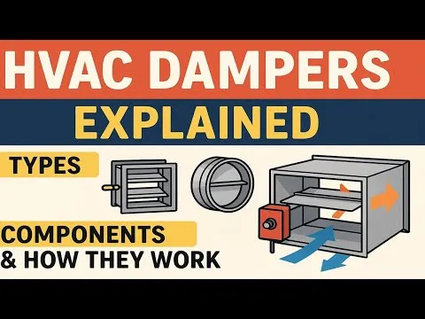
The Shortest Answer
Damper definition: an adjustable assembly of plates and blades inside ductwork intended for regulating air volume. Thus, what is a damper in HVAC? It is the same device used for modulating or controlling air in commercial or industrial air systems.
What This Article Covers
- Definition and principle of operation of the device
- Main types and their areas of application
- Control principles of air balancing
- Manual or electric operation
- Choice and sizing
- Installation, commissioning and FAQs
What Is a Damper? Definition and Core Function
A damper is defined as a movable blockage inside a ductwork. What does a damper do? It modifies the free area, adding some resistance to the airflow in a duct. That is what needs to be said regarding its functioning.
A damper must have three distinctive features: a movable blade that changes free area and provides a variable resistance. So what is an HVAC damper without these features?
They serve the same role in air systems as valves do in water systems. Dampers do not create the flow of air; instead, they create a resistance to the flow.
The Damper Definition in Plain Terms
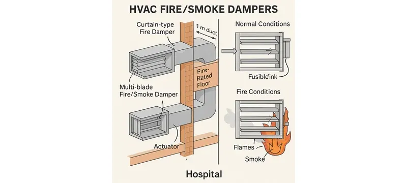
A damper is an appliance that consists of one or several blades, which can twirl around. By doing so, it changes the free area that modifies the resistance to air.
What is a damper HVAC? It is the very instrument that modulates the incoming air. In layman's terms, what is a damper but an obstacle present in a duct that can easily be controlled.
What Does a Damper Do in an HVAC System?
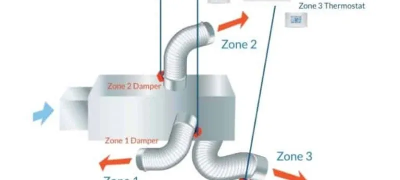
In what manner does a damper function? What does a damper do in practice? It manages airflow from various branches, forms zones, governs outside air, and assists in containing smoke and fire.
The above four tasks cover most of the functions of dampers.
- Manage airflow from different branches of ducting in HVAC
- Form sections of ducting for maintenance
- Control intake of outdoor air
- Help in smoke and fire containment
Dampers vs Valves: One Key Distinction
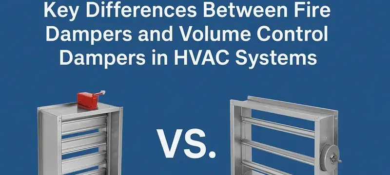
Dampers regulate air, while valves control water or steam. The stances are similar, but the measurements are different. What is a damper? It is an air-side instrument, and what are dampers but the air-side counterpart to valves.
Do not confuse the valve for a damper in the system.
Airtight dampers guarantee that the leakage is less than 0.5% according to the JB/T 7228-94 standard [15]. The measurement for water valves is made using a completely different medium and pressure measurement; the figures cannot be correlated whatsoever.
Main Damper Types and Where EACH Belongs
There are several categories of damper, among them volume control, CAV, three-way split, and zone dampers. Types of safety damper include fire, smoke, and combination.
The pressure control damper category includes relief and backdraft types.
Terminal modulation is characteristic of both VAV and CAV dampers. What is an HVAC damper within a VAV system? It is the modulating component providing the required flow rate to the zone. Each type has its own Requirements and leakage standards, so what are dampers in HVAC but duty-matched components.
Volume Control Dampers (VCDs)
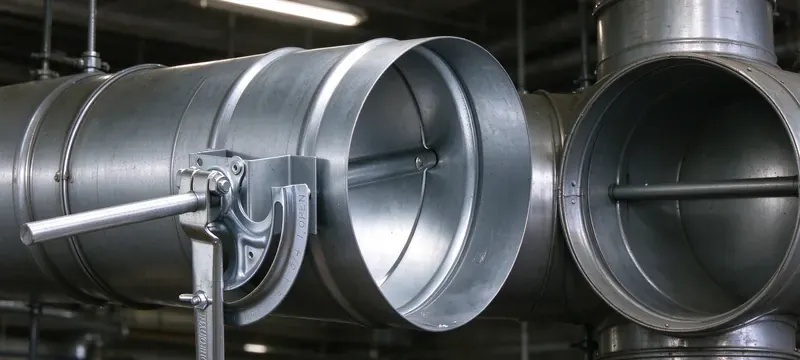
VCDs are considered the workhorses of the industry. They come with either manual or motorised operation. What are hvac dampers used for in balancing schemes? VCDs are the most common choice.
Deiiang provides both opposed blade and parallel blade devices for rectangular duct types. Opposing blades make it possible for linear control while parallel blades achieve complete shutoff at the same angle.
For small circular ducts a single blade butterfly damper is used while three-way split dampers support preliminary balancing. An airtight oblique-insertion slide damper is used in purification and dust extraction systems.
A constant air volume damper keeps branch volume at a constant level regardless of pressure variations occurring within a duct. Zone and bypass damper options make use of zone-based comfort systems. Each of these damper types is a variant of a VCD, and each one answers what are dampers for hvac balancing duty.
- Manual or motorised
- Use of single leaf for small round duct types
- Use of multi leaf for rectangular ducts
- Opposing blades used for linear control purposes
- Parallel blades allow for tight shutoff
Fire Dampers, Smoke Dampers and Combination Dampers
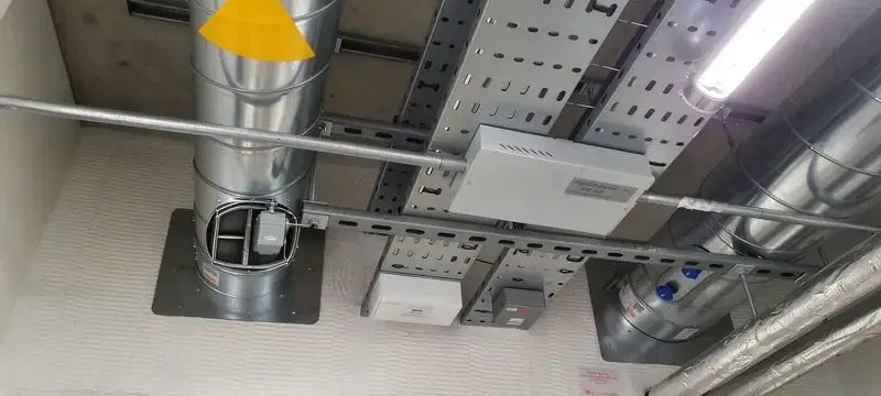
Fire dampers do the closing with the application of heat. Smoke dampers prevent leakage. Combined units do both functions. What are dampers of this type? They are units used to protect lives.
According to UL 555 [5] the fire resistance is assessed for 1.5 or 3 hours depending on a listing. Class I, II, and III smoke leakage are defined by UL 555S. Class I is the tightest leakage class.
NFPA 90A regulates how HVAC systems are set up. NFPA 92 outlines smoke control methods. EN 15650 is the European fire damper standard.
- The UL 555 rating system
- UL 555S levels of smoke leakage according to the classification of I, II, or III
- Regulations according to NFPA 90A and NFPA 92
- EN 15650
- According to the IMC and the International Building Code
- Fire and smoke combinations
Pressure Relief, Backdraft and VAV Dampers
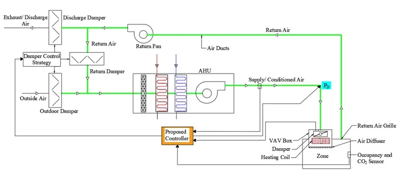
Pressure relieving dampers save space from pressure build up. Backdraft dampers help prevent flow reversal. VAV terminal dampers can control the supply of air.
There are also airtight oblique-insertion slide dampers used for purification and extraction of dust. There are also CAV dampers which maintain the volume of airflow through the duct against duct pressure swings. So what are dampers hvac engineers turn to for pressure duty? These relief and backdraft units.
Comparison Table: Damper Type vs Duty and Leakage
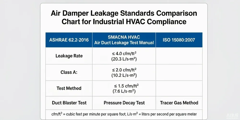
Table 1: Damper type versus duty, leakage, standard, and location.
| Damper Type | Main Use | Standard Leakage Class | Applicable Standard | Common Placement |
|---|---|---|---|---|
| Volume control | Control airflow | AMCA 500-D Class 1A to 3 | AMCA 500-D | Branch ducts |
| Fire | Prevent fire spreading | Not applicable; fire endurance of 1.5 hours or 3 hours | UL 555 | Fire compartment walls |
| Smoke | Control smoke leaks | UL 555S Class I | UL 555S | Smoke control zones |
| Pressure relief | Maintain pressure | AMCA 500-D Class 1A to 3 | AMCA 500-D and AMCA 511 | Return or relief ducts |
| VAV terminal | Control the flow | EN 1751 Class 1 to 4 | EN 1751 | VAV devices |
| Damper Type | Main Use | Standard Leakage Class |
|---|---|---|
| Volume control | Control airflow | AMCA 500-D Class 1A to 3 |
| Fire | Prevent fire spreading | Not applicable; 1.5 h or 3 h endurance |
| Smoke | Control smoke leaks | UL 555S Class I |
| Pressure relief | Maintain pressure | AMCA 500-D Class 1A to 3 |
| VAV terminal | Control the flow | EN 1751 Class 1 to 4 |
How a Damper Actually Controls Airflow
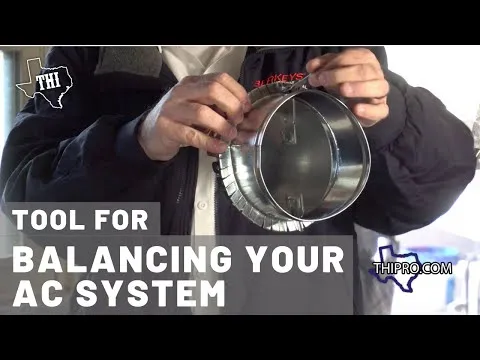
The operation of a damper consists in changing the angle of the blades which changes the free area and consequently the resistance of the airflow. As the blades cover, the free area becomes smaller and the pressure loss becomes higher.
A damper does not create the flow; it modulates it. That is exactly what does a damper do at its most basic level.
What does an HVAC damper control at partial load? It regulates the flow going to a zone. The connection between the flow and the pressure loss is quadratic. Thus a minute change in the angle of blades that are nearly closed has a great impact on the flow decrease.
CCY11 differential-pressure transmitter can monitor this process. Deiiang control panels rely on an S7-200 SMART PLC to record and control these parameters.
Blade Angle, Free Area and Pressure Drop
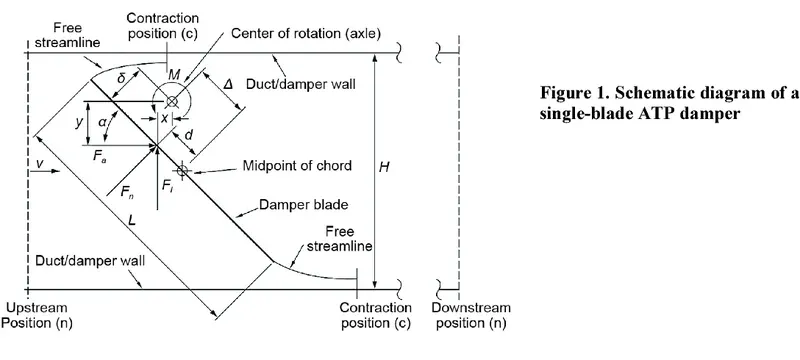
When the duct is fully opened, it results in pressure drop to the minimum extent. However, partially closing the duct causes something which increases the pressure drop. The relationship between airflow and the pressure drop is quadratic.
When the tilt of blades changes no more than 30 degrees from the maximum opening position, the area gets reduced by more than fifty percent. That is why the commissioning process calls for measuring the angle of blades and not only the precise airflow.
- The fully open duct causes minimal pressure drop
- The partially closed duct faces higher resistance
- Existing dependency is quadratic
- The face velocity cannot exceed 20 m/s
Leakage, Blade Gap and Airtightness Classes
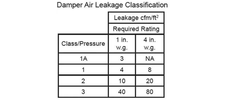
Leakage hardly matters when the duct is open. The open/closed blade position will determine the airflow through the basis of the AMCA 500-D standard with distinct classes of leakage: the class with the lowest leakage and the class with the greatest leakage.
The classification process results in the classification for the air leakage provided by Deiiang catalogue data: less than 2% leakage in normal mode and less than 0.5% leakage in airtight mode per JB/T 7228-94.
The data shows the gap smaller than 2 mm and flow less than 20 m/s for a fully open valve.
Mechanical changes will be determined above 1.2 m² as the new device will be supplied in the assembled design. The blade coaxiality deviation will be approximately 2 per mille in all cases. Also, the device should not vibrate in the closed state. What is a damper that leaks at this point? It is simply a failed damper.
Table 2: Classes of leakage based on AMCA and EN standards.
| Standard | Category | Leakage level | Test pressure |
|---|---|---|---|
| AMCA 500-D | Category 1A | Tightest | 1 inch wg closed |
| AMCA 500-D | Category 1 | Very low | 1 inch wg closed |
| AMCA 500-D | Category 2 | Low | 1 inch wg closed |
| AMCA 500-D | Category 3 | Moderate | 1 inch wg closed |
| EN 1751 | Category 1 | Lowest | 1000 Pa |
| EN 1751 | Category 2 | Low | 1000 Pa |
| EN 1751 | Category 3 | High | 1000 Pa |
| EN 1751 | Category 4 | Tightest | 1000 Pa |
| Standard | Category | Leakage level |
|---|---|---|
| AMCA 500-D | Category 1A | Tightest |
| AMCA 500-D | Category 1 | Very low |
| AMCA 500-D | Category 2 | Low |
| AMCA 500-D | Category 3 | Moderate |
| EN 1751 | Category 1 | Lowest |
| EN 1751 | Category 2 | Low |
| EN 1751 | Category 3 | High |
| EN 1751 | Category 4 | Tightest |
Damper Authority: Why Size Matters More Than You Think
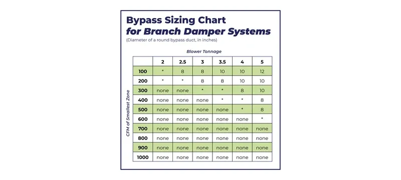
The authority refers to the open damper pressure drop divided by the entire system pressure drop. The end goal is to obtain a value of 0.3 to 0.5. An HVAC damper with low authority cannot modulate effectively since much of the system resistance is located elsewhere.
Consequently, an installation with an authority of 0.25 will constantly oscillate around the setpoint. The solution to this condition is simple arithmetic. Introducing 30 Pa of open resistance will yield a ratio of 80 / 230 or 0.35, positioned within the target limits.
Calculating Damper Authority
Example: ΔP_damper open = 50 Pa, ΔP_total = 200 Pa. Authority = 50 / 200 = 0.25. Low authority leads to limitations in modulation. Increase damper resistance or resize it.
Manual vs Motorised and Automatic Damper Operation
How do HVAC dampers operate? There are both manual and motorised dampers. Manual dampers rely on quadrant handles, and the motorised units use actuators.
The table below synthetically compares both types.
What do HVAC dampers accomplish in critical zones of operation? They are required to provide fail-safe operation, which leads to spring-return actuators. General comfort branches allow both manual units that can be set once and forgotten. That is the practical answer to what are hvac dampers in terms of operation.
Table 3: Manual Dampers versus Motorised Dampers
| Feature | Manual Damper | Motorised Damper |
|---|---|---|
| Actuation | Hand-operated | Powered actuator |
| Power Supply | None | 24V or 230V |
| Fail-safe | None | Spring powered fail-safe |
| Control | Fixed setting | Variable control |
| Approximate cost (indicative) | 1x | 2x to 4x with wiring |
| Installation | Necessary for adjustment | Necessary for wiring |
| Feature | Manual Damper | Motorised Damper |
|---|---|---|
| Actuation | Hand-operated | Powered actuator |
| Power Supply | None | 24V or 230V |
| Fail-safe | None | Spring powered fail-safe |
| Control | Fixed setting | Variable control |
| Approximate cost (indicative) | 1x | 2x to 4x with wiring |
| Installation | Necessary for adjustment | Necessary for wiring |
Manual Dampers and Locking Quadrant Handles
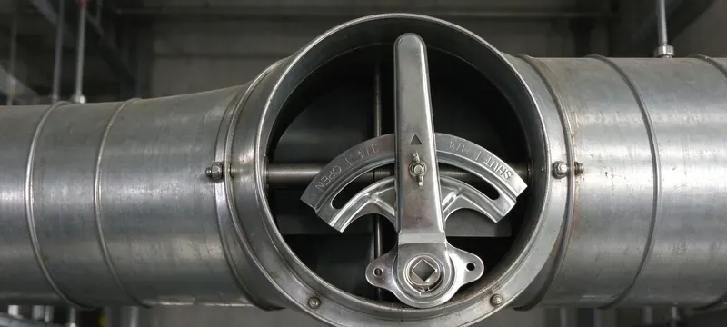
Concerning the articles hereafter, manual dampers are set-and-forget types. The system at Deiiang uses a locking quadrant handle to lock the damper in position, proactively preventing any unintended motion.
Moreover, codes rather than preferences create the need for an access hatch, which allows for the adjustment of the balance setting to achieve a desired performance.
- Set-and-forget balance
- Locking quadrants and no motion
- Low initial cost
- Access hatch needed due to codes
Motorised Dampers and Actuator Selection
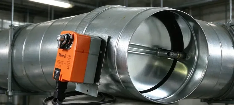
Now concerning the function of motorized dampers. Motorized models use actuators to perform their function. In the case of spring return, one could say that spring return gives the fail-safe option.
In the case of torque, it is dictated by the pressure and blade area. So, e.g., in the case of a 0.6 m² blade in 500 Pa, approximately 30 N·m of torque is needed.
The options listed by Deiiang include a 220 V actuator with 30 N·m of torque and a high torque model of 24 V rated for 250 N·m and built for the cases where large blade areas are involved.
- Spring return to create fail-safe
- 24V AC/DC or 230V
- Torque dictated by blade area and pressure
- Running time approximately 30-90 seconds
- Living up to humid environment IP rating
According to Deiiang's catalogue data, it appears that the running time may be set to 5, 8, 15, 30, 50, or 100 seconds. The 220 V actuator can run delivering 30 N·m in 20 seconds. The 24 V high torque one can output at the level of 250 N·m in 30 seconds, yet both have IP67 rating in respect to the temperatures varying from -30 to +60 degrees Celsius.
Damper Selection and Sizing for Real Projects
The first step in the selection process is the airflow and duct size. What are dampers for HVAC projects? They should satisfy the requirements for leakage, velocity, and pressure.
The selection of dampers for HVAC systems without these measurements would be convoluted.
Deiiang publishes relevant collections in specific groups such as Volume Control Dampers, Motorised HVAC Dampers, Fire and Smoke Dampers, Backdraft and Gravity Dampers, and Zone Dampers. Each collection belongs to a particular usage.
Case in the project: the zoned variable air volume (VAV) system could not maintain its airflow along the branches; terminal boxes hunted; and the fan followed its fan curve. Following the installation of the opposed blade volume dampers and rebalancing, deviation rates dropped from plus or minus 25% to plus or minus 10%. This outcome is project-reported, not a verified field measurement.
Step-by-Step Damper Selection Procedure
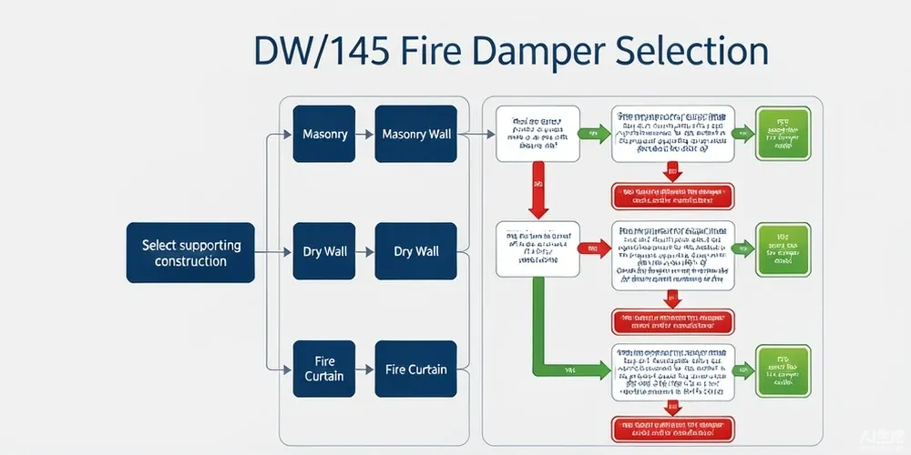
Sizing Selection Matrix
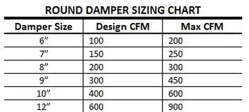
Table 4: Matrix for sizing selection.
| Use | Recommended Type of Damper | Leakage Class | Face Velocity Limits | Pressure Drop Requirements | Type of Actuator |
|---|---|---|---|---|---|
| General comfort | VCD | AMCA Class 2 | 1500 fpm | 25-50 Pa | Mechanical |
| clean room critical | Low leakage VCD | AMCA Class 1A | 1000 fpm | 50 Pa | Motorized |
| Smoke control | Smoke damper | UL 555S Class I | 2000 fpm | 50 Pa | Spring powered |
| Use | Recommended Type of Damper | Leakage Class |
|---|---|---|
| General comfort | VCD | AMCA Class 2 |
| Clean room critical | Low leakage VCD | AMCA Class 1A |
| Smoke control | Smoke damper | UL 555S Class I |
Deiiang Localisation Data for Selection
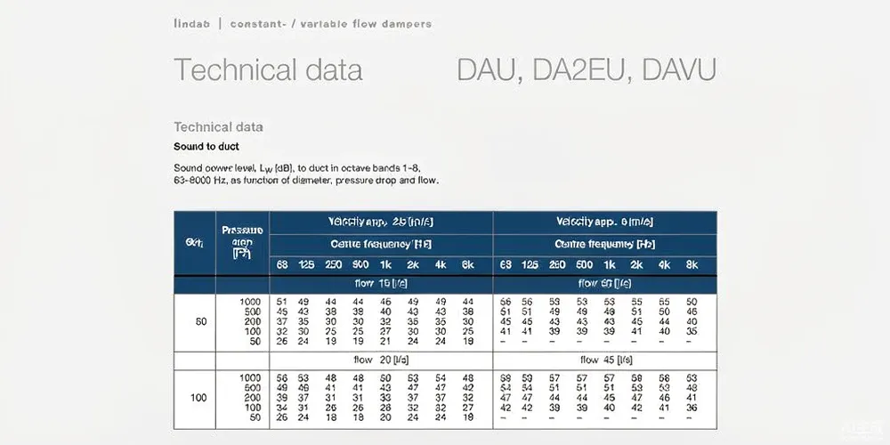
Deiiang cleanroom Technology presents the data in its catalogue under the name of designer Jason Peng. The VCD leakage is totally less than 4 cfm/ft² in terms of operational pressure through a blade gap which is of about 2 mm. The face velocity shows up to 10 m/s in catalogue data.
CCY11 must be able to monitor all pressure in the range of -100 to +100 kPa with 0.25%, 0.5% or 1% FS accuracy. Its outputs include 4-20 mA, RS485 and 0-10 V since this is catalogue data. What is a damper hvac buyers should pick? This selection matrix is where that decision is made.
Installation, Commissioning and Site Faults
Installation for fan and air wash systems follows GB 50243-2016 [13] in use whereas JG/T 14-2010 [14] is what the air terminal is governed by. In this connection, the air terminal references GB 50243-2016 [13], which sets the standards for airflow measurement.
However, using the pamphlet literature referenced might create problems if the blowing is not accompanied by airtight installation defects. For example, JB/T 7228-94 [15] is for leakage testing of ventilation systems only and must be read along with installation procedures.
Without commissioning the venting section of the ventilating system is prone to be damaged. Ventilators without commissioning create uncontrolled leakage. Below are the rules as per SMACNA and the Chinese duct component guide on installation of ventilating equipment. Every professional knows what is an hvac damper worth when it is installed badly.
Installation Essentials and Code Requirements
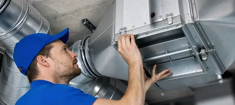
Frames must be square and free of any racks. Direction of flow should be correct so that there is easy access.
If a handwheel is made from wood, it should be positioned 1.5-1.8 m with clearances of 200 mm. It is forbidden to bury a damper in the wall at the structural level. A Constant Air Volume (CAV) body remains in horizontal position, maintaining the level of 2 per mille.
The data on straight duct and tolerances ensure the quality of control being not exceeded. It is necessary to allow 1.5x duct width on the upstream side of the CAV equipment and 0.5x downstream of the CAV equipment. Damper level tolerance is 3 per mille, plumb tolerance is 2 per mille with distance between bolts of 150 mm.
Gaskets must follow the same requirements. 3 mm can be used, or 4-6 mm in case of purification systems. Use of foam plastICs, thick cardboard, asbestos rope, and felt is not allowed. Gaskets shall not be painted.
The table below provides the tolerances and limitations for the systems being in accordance with the state norms.
Table 5: Tolerances and limits per GB 50243-2016.
| Name | Requirements/limits | Legislation |
|---|---|---|
| Divergence between the blade and the case | Below 2 mm | GB 50243-2016 [13] |
| Damper tilt | 3 per mille | GB 50243-2016 [13] |
| Damper plumb | 2 per mille | GB 50243-2016 [13] |
| Distance between bolt flanges | 150 mm | GB 50243-2016 [13] |
| Offset of fire damper from the wall | 200 mm | GB 50243-2016 [13] |
| CAV horizontal position | 2 per mille | GB 50243-2016 [13] |
| Name | Requirements/limits | Legislation |
|---|---|---|
| Divergence between the blade and the case | Below 2 mm | GB 50243-2016 [13] |
| Damper tilt | 3 per mille | GB 50243-2016 [13] |
| Damper plumb | 2 per mille | GB 50243-2016 [13] |
| Distance between bolt flanges | 150 mm | GB 50243-2016 [13] |
| Offset of fire damper from the wall | 200 mm | GB 50243-2016 [13] |
| CAV horizontal position | 2 per mille | GB 50243-2016 [13] |
Commissioning Checklist for Dampers
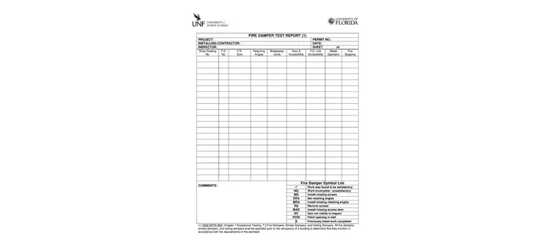
As to motorized dampers, they get separate tests by leakage and dry run as a whole system. Electric checks include the following: insulation resistance, grounding resistance, dielectric break, voltage in operation, controlling signals.
Common Site Faults and How to Avoid Them
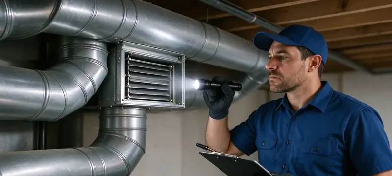
Oversized damper has better controllability.
Reality: authority lower than 0.3 leads to oscillations.
Manual damper does not require access.
Fact: access is needed for code compliance.
Actuator torque is sufficient.
Fact: blade area and pressure control the torque.
Any damper can stop smoke.
Fact: only devices with UL 555S listing can perform that job.
What are the causes of failures of dampers? Four things cover most of the site issues.
Table 6: Fault, cause, check and way to fix it.
| Symptoms | Probable cause | Check | Solving problem |
|---|---|---|---|
| Hunting | Authority below 0.3 | Compare open dP and total DP | Add resistance or remodel the damper |
| Leaking when closed | Worn seals or distorted frame | Measure the gap | replace seals or adjust frame |
| Noise | High airflow or vibrations | Check airflow and play of valves | Decrease speed, tighten connections |
| Blocked damper | Stuck joints or foreign bodies | Check by hand | Clean, align and lubricate joints |
| Symptoms | Probable cause | Solving problem |
|---|---|---|
| Hunting | Authority below 0.3 | Add resistance or remodel the damper |
| Leaking when closed | Worn seals or distorted frame | replace seals or adjust frame |
| Noise | High airflow or vibrations | Decrease speed, tighten connections |
| Blocked damper | Stuck joints or foreign bodies | Clean, align and lubricate joints |
Fault 1 — Low Damper Authority
Fault 2 — Leaking in Closed Position
Frequently Asked Questions
These are the questions that people search for. All answers consist of keywords.
What Is a Damper in Simple Terms?
The damper refers to an adjustable plate that is utilized in a duct to control the intensity of airflow being supplied. The definition of damper can thus be stated as a way to obstruct the air as per necessity. What is a damper in HVAC? It is that same adjustable plate inside a commercial or industrial air system.
What Does a Damper Do in an HVAC System?
One may ask what does a damper do? Dampers help in balancing the flow of air and creating sections to separate airflow, controlling the fire and smoke. However, they alone do not create any airflow as their purpose is only to create an obstacle against the incoming air.
What Are the Main Types of HVAC Dampers?
The different types of dampers can be mentioned as volume control dampers, fire dampers, smoke dampers, pressure relief dampers, and VAV dampers. Each of these dampers serves a different purpose, and each answers what are dampers in HVAC terms.
How Do I Choose Between Manual and Motorised Dampers?
For manual dampers, one may keep using them on a long-term basis without altering the position of the dampers while the motorized dampers provide control features with permissible authority limits between 0.3 to 0.5. It is also advised to examine the torque requirements of the actuators being used and whether there is an assurance for fail-safe features.
What Leakage Class Should I Specify?
The recommended leakage class for normal applications is AMCA Class 2 but for critical areas like cleanrooms AMCA Class 1A or EN 1751 Class 3 or 4 would be more suitable as it ensures that the gap between the blades is less than 2 mm.
What Standards Govern Damper Testing and Installation?
The standards that govern the testing of dampers include AMCA 500-D [1], UL 555 [5], UL 555S [6], NFPA 90A [7], NFPA 92 [8], EN 1751 [9], EN 15650 [10], ASHRAE 90.1 [3], and GB 50243-2016 [13].
References
- [1] AMCA 500-D, Laboratory Methods of Testing Dampers for Rating.
- [2] ASHRAE 62.1, Ventilation for Acceptable Indoor Air Quality.
- [3] ASHRAE 90.1, Energy Standard for Buildings.
- [4] SMACNA, HVAC Duct construction Standards.
- [5] UL 555, Fire Dampers.
- [6] UL 555S, Smoke Dampers.
- [7] NFPA 90A, Installation of Air-Conditioning and Ventilating Systems.
- [8] NFPA 92, Smoke Control Systems.
- [9] EN 1751, Ventilation for Buildings — Air Terminal Devices.
- [10] EN 15650, Fire Dampers.
- [11] IMC, International Mechanical Code.
- [12] IBC, International Building Code.
- [13] GB 50243-2016, Construction Quality Acceptance for Ventilation and Air Conditioning.
- [14] JG/T 14-2010, Air Terminals for Ventilation and Air Conditioning.
- [15] JB/T 7228-94, Damper Leakage Test Method.