+86 13638632902
 Jason@cleanroomequips.com


 MENU
MENU
In brief, HVAC systems employ different types of dampers. The types of HVAC dampers include volume, control, fire, smoke, combination fire-smoke, barometrIC, backdraft, zone and cleanroom isolation dampers. EACH one has a distinct job.
This manual looks at the different types of dampers and how they work, plus the factors to weigh when choosing the right one.
You will also find the purposes and specifications behind each family. By the end, you should be able to settle three decisions: type, size and fail position.
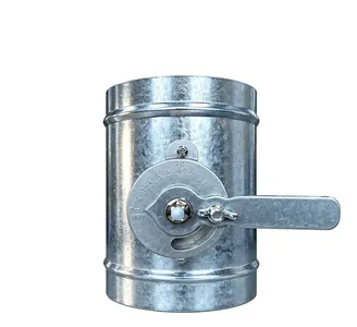
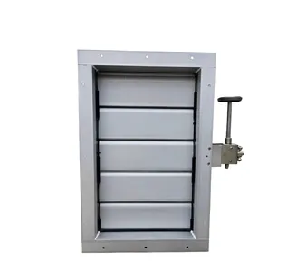
air flow control valve
Airflow control valve delivering precise, repeatable air volume regulation.
Send inquiry Now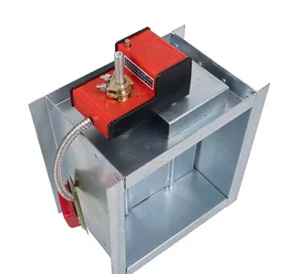
pressure relief damper
Pressure relief damper operating automatically to protect ducts from
Send inquiry Now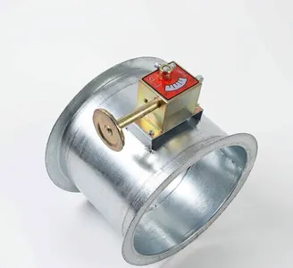
Short answer: the main types of dampers are volume, control, fire, smoke, combination fire-smoke, barometric, backdraft, zone and cleanroom isolation. Most homes need only two or three of them.
The Short Answer: What Are the Main Types of Dampers?
HVAC damper types fall into nine main families. Common types of dampers used in homes are usually just two or three of them.
- Volume damper: balances airflow in a branch.
- Control damper: modulates airflow with an actuator.
- Fire damper: closes on heat to protect a rated wall.
- Smoke damper: closes when smoke is detected.
- Combination fire-smoke damper: performs both duties.
- Barometric damper: relieves excess pressure.
- Backdraft damper: stops reverse flow at a fan.
- Zone damper: opens or closes a conditioned zone.
- Cleanroom isolation damper: seals a critical ventilation run.
Other kinds of dampers in hvac include constant air volume, three-way split, pressure-relief and airtight slide dampers. Deiiang™ supplies all of these from one catalogue.
Who This Guide Serves and How to Use It
This guide denotes the five parties involved. Contractors engage in installing the duct. MEP engineers take references from the tables for dimensions and authority. Commissioning agents crave information about the testing methods. Facility managers refer to the guide for troubleshooting. Procurement buyers refer to the guide to find the specifications they need.
What an HVAC Damper Is and How It Controls Airflow
An HVAC damper is described as a device that contains movable wings. These wings are housed in the duct system, frame, or wall opening. The modifiable section of the device affects the flow of air due to changes in the free area. All variants of dampers in HVAC systems are based on the same idea.
There are three fundamental features, which are: the angle of blades, drop of pressure, and leakage.
However, in terms of design, damper of any type must include a blade, a frame, and an operation mechanism. The simplest version is manual dampers, while the most complicated are certified assemblies for smoke and fire control.
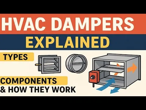
Damper characteristICs to check:
- Blade angle from 0° to 90°.
- Free area versus duct cross-section.
- Pressure drop at design velocity.
- Leakage class when closed.
- Authority level over the branch.
Damper Function in an Air Distribution System
A damper fulfills four functions: Balancing, which steers air into different branches; isolation, which stops flow so that maintenance can be done; modulation, which operates according to a thermostat or pressure signal; and fire and smoke protection, which kicks in when the alarm goes off.
Ducts' static pressure interacts with the fan curve in each damper, causing the static pressure to rise elsewhere when one of the branches is closed, meaning that the fan might operate on a higher part of the curve. Each damper type must be evaluated against its whole system.
Blade Angle, Pressure Drop and Flow Authority
The angle in which blades are set is not the same with every manufacturer. Make sure that the open and closed positions for the model are as indicated in the schematic drawings. A damper can close completely but allow some leakage, depending on the sealing efficiency and construction of the damper and the differential pressure.
The pressure drop increases proportionately to the square of the velocity: ΔP = K × 0.5ρv² where K represents the loss coefficient, ρ is the air density (which is approximately 1.2 kg/m³), and v is the velocity (face velocity). Hence, with the doubling of the velocity, ΔP quadruples.
Authority is the proportion of total branch resistance that pertains to the damper. If the authority of a damper is low, it will fail to control air flow efficiently. When a damper is used for modulating duty, aim for authority greater than 0.3.
The Different Types of Dampers in HVAC Systems
The clearest method to compare different categories of HVAC dampers is through a table. Table 1 outlines the duty rating, leakage class, location, actuator Type And references for each group. Although some types of dampers use similar hardware, their Certifications differ.
The three questions that must be answered before looking at the table are: What is the anticipated duty? What leakage class does the regulation or process require? Finally, what fail position does the life-safety plan stipulate?
By answering these questions, we reduce the number of families that need to be analyzed to two or three.
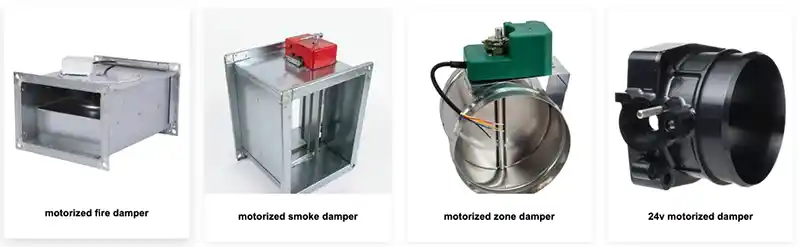
Table 1: Damper families by duty, leakage, location, actuator and primary reference
| Damper type | Duty | Leakage | Location | Actuator | Primary reference |
|---|---|---|---|---|---|
| Multi-leaf volume | Balance | General <2%, tested per JB/T 7228-94 | Branch duct | Manual or electric | JG/T 14-2010 |
| Single-leaf butterfly | On/off | General | Terminal run | Manual or electric | JG/T 14-2010 |
| CAV | Constant volume | General | Branch | Pneumatic or electric | JG/T 14-2010 |
| Control (modulating) | Modulate | General or airtight | VAV box inlet | Electric | AMCA 500-D |
| Fire | Fire protection | Fire class I/II/III | Rated wall | Fusible link | UL 555 |
| Smoke | Smoke control | Leakage class I/II | Smoke barrier | Electric | UL 555S |
| Combination fire-smoke | Both | Fire class plus leakage class | Rated wall plus smoke barrier | Electric plus link | UL 555 / 555S |
| Barometric | Pressure relief | General | Relief opening | Self-acting | SMACNA |
| Backdraft | Reverse-flow stop | General | Fan outlet | Self-acting | SMACNA |
| Zone | Zoned comfort | General | Branch to zone | Electric | IMC |
| Bypass | Static pressure relief | General | Zone trunk | Electric | IMC |
| Three-way split | Initial balancing | General | Main and branch | Manual | JG/T 14-2010 |
| Pressure-relief | Over-pressure control | General | Standalone room | Self-acting or electric | SMACNA |
| Airtight slide | Isolation | Airtight <0.5%, tested per JB/T 7228-94 | Dust extraction or purification | Electric | EN 1751 |
| Cleanroom isolation | Airtight isolation | Airtight <0.5% | Exhaust or supply | Electric | EN 1751 |
[Duplicate simplified table removed — was rendered twice on the live page.]
It must be noted that AMCA 500-D and SMACNA are standards of testing and building references, however, product listing standards are provided by the UL, EN, or the relevant building codes.
Fire damper class and smoke leakage class coming from different systems mean that one should not look at fire classes as leakage class or vice versa.
The other types of dampers used in HVAC systems are the three-way split and pressure relieving damper. The Deiiang catalog has leakage and torque rating of each of the mentioned systems.
Volume, Manual Balancing and Control Dampers
A volume damper is a crucial part of the HVAC system. A manual locking quadrant model is less expensive to produce and does not require any electricity to operate. A balancing contractor sets the damper blade and locks it in place.
Control dampers have an added actuator that runs on electricity. They can modulate airflow anywhere between 0% and 100% according to a 0-10 V or 4-20 mA signal. Within a VAV-system, control dampers operate as the primary regulators of airflow.
Three interconnected categories of damper perform more specific tasks. A CAV damper maintains constant airflow while duct pressure fluctuates. A three-way split damper divides air between the main duct and a branch duct while balancing airflow at first. Pressure-relief dampers release air when pressure exceeds a certain level.
Short list of duties:
- Manual volume: balance once, then leave alone.
- Control: follow a thermostat or pressure loop.
- CAV: hold constant volume despite pressure changes.
Fire, Smoke and Combination Fire-Smoke Dampers
Fusion links cause fire dampers to close when heat is sensed, while smoke dampers react to detection signals. Hybrid devices perform both tasks, receiving a dual listing.
Code traps to avoid:
- UL 555 covers fire dampers; UL 555S covers smoke dampers [5][6].
- NFPA 90A governs air-conditioning duct systems [7].
- NFPA 92 governs smoke control systems [8].
- EN 15650 and EN 1751 apply in European projects [9][10].
- IBC and IMC set installation and location rules [11][12].
- Fail-safe position must match the life-safety strategy.
It should be noted that the task of maintenance does not lie solely with the installation team. NFPA 80 requires verification of the proper function of fire dampers. NFPA 105 meets similar Requirements for smoke dampers.
Testing is carried out once a year or according to the results.
Pressure, Backdraft, Zone and Cleanroom Isolation Dampers
A barometric type of damper is used to relieve excess pressure, without electricity. A backdraft damper is used to stop reverse flow on the outlet of the fan. A zone damper is the one used to close or to open the zone of a home or light commercial building. A cleanroom isolation damper serves for sealing the critical run in case of exhaust.
Bypass is very important to have in zone systems. In the case of several zone dampers being closed simultaneously, the static pressure rises very rapidly.
A bypass damper itself opens in order to send that excess air through it, and also maintains static pressure at the level of setpoint. Without it, zone dampers may make noise, and the fan would consume some energy unreasonably.
Different dampers differ in their class of leakage as well as actuator. As the Deiiang™ catalogue shows for its airtight slide dampers, the leak rate of them is less than 0.5% according to JB/T 7228-94. Regular dampers have a leak rate of less than 2%.
Manual vs Motorised: HVAC Damper Types by Operation
The operation divides the market into two categories. In fact, the most common dampers used in residential HVAC systems are manual, while those in commercial systems are automatic. What are the main types of dampers used in the US market? Generally, they are classified as manual volume, zone, barometric and backdraft dampers.
The market differentiates types of HVAC dampers by the way of operation in the first place.
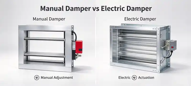
Table 2: Manual versus motorised operation
| Operation | Actuator type | Torque | Response time | Fail action | Cost | Typical use |
|---|---|---|---|---|---|---|
| Manual | Locking quadrant | Hand force | Minutes | None | Low | Balancing |
| Electric on/off | Electric (220 V) | 30 N·m | 20 s | Optional | Medium | Isolation |
| Electric modulating | Electric (220 V) | 30 N·m | 20 s | Optional | Medium | VAV control |
| High-torque electric | Electric (220 V) | 250 N·m | 30 s | Optional | High | Large ducts |
| Pneumatic | Air piston | Project-specific | Variable, project-specific | Spring-return | Medium | Legacy plants |
| Electric spring-return | Electric plus spring | 30 N·m | 15 s | Fail-closed or fail-open | Medium | Fire-smoke |
[Duplicate simplified table removed — was rendered twice on the live page.]
The Deiiang™ electric options selected for this order feature response times of 5 sec, 8 sec, 15 sec, 30 sec, 50 sec and 100 sec. Pneumatic response time depends mainly on volume of tube and pressure of supply.
Manual Dampers: Where They Still Make Sense
Manual dampers still make sense in certain occasions when it comes to one-off balancing, low-cost residential branches, and locations without electricity. A commissioning agent sets the flap and marks the same position.
Reasons to keep manual units:
- No actuator to fail.
- Lowest first cost.
- Works during power loss.
- Easy to verify visually.
Motorised Actuators: Electric, Pneumatic and Spring-Return
Deiiang™ motorized actuators come in a couple of catalogue sizes. The standard model is an AC actuator rated at 220 V, 8 W, 0.036 A, 30 N·m, 20 s, and IP 67 compliance. The high torque Model of type 25 is rated at 24 V DC 50 W, 3.57 A, 250 N·m, 30 s, and is also IP 67 compliant.
Both models have insulation resistance of not lower than 1 MΩ and vice the dielectric test at AC 1500 V according to the class H insulation system. The ambient temperature range is from -30 to +60 degrees Celsius with glands of M16x1.5 and PG 13.5 configurations.
Among the possible control modes available are on/off, passive contact, proportional and intelligent self-adjusting. The devices have built in safety features like limit switches, thermal protection and over-torque protection.
Table 3: Actuator torque selection by face area, catalogue data
| Face area band | Recommended torque | Notes |
|---|---|---|
| Up to 0.5 m² | 30 N·m | Standard electric model |
| 0.5 to 1.2 m² | 30 N·m | Verify breakaway torque |
| Above 1.2 m² | 250 N·m | Grouped assembly, 25-type |
| Any band | Breakaway torque × 1.5 | Round up to next catalogue value |
[Duplicate identical table removed — was rendered twice on the live page.]
Fail-Safe and Fail-Position Logic
Fail-safe mechanism implies that the pneumatic damper adjusts itself in a safe position when it encounters a loss of power or signal. Fail-closed fittings are suitable for smoke diversion purposes and fail-open fittings are used for air supply.
The assumption of every pneumatic damper failing closed is not true. The position of the valve depends on the safety plan. For instance, NFPA 92 requires that the documentation of smoke control design states the fail position of the valve.
Per NFPA 92 §6.3.4, fail-safe position must be explicitly specified in the design documents and verified during acceptance testing — it is not a default setting.
The myth that spring-return could be used in all cases is not correct; it is used only in applications that demand this mechanism.
Per AMCA Publication 500-D §7.2.3, spring-return actuators are rated only for specific torque ranges and differential pressures; they must not be substituted for standard electric actuators outside their rated envelope.
Damper Sizing, Leakage, Pressure Drop and Authority
Sizing doesn't only rely on duct size; it also takes other aspects into account such as face velocity. A damper that's small will create high pitch sound while oversizing a damper will take away control of it. The forms of dampers used in hvac pdf provide these limits in tabular form.
Use the table below to provide an initial evaluation and confirm it against the project's schedule. The torque range of 10-15 N·m and 60-100 N·m serves as only examples and not actual values listed in catalogue of Deiiang™.
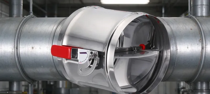
Table 4: Sizing matrix by duct size and duty
| Duct size (mm) | Face velocity (m/s) | Max pressure drop (Pa) | Leakage class | Actuator torque | Application |
|---|---|---|---|---|---|
| 200 × 200 | 5-8 | 40 | General | 30 N·m | Residential branch |
| 400 × 400 | 8-12 | 60 | General | 30 N·m | Commercial branch |
| 600 × 600 | 10-15 | 80 | General | 30 N·m | Main branch |
| 800 × 800 | 12-18 | 100 | Airtight | 250 N·m | VAV inlet |
| 1000 × 1000 | 15-20 | 120 | Airtight | 250 N·m | Large plant |
| 1200 × 1200 | ≤20 | 150 | Airtight | 250 N·m | Cleanroom exhaust |
[Duplicate simplified table removed — was rendered twice on the live page.]
Face Velocity and Pressure-Drop Sizing
In order to keep face velocity consistent with less than 20m/s at the fully opened position, it was strictly mentioned in the Deiiang™ catalog.
The formulas for estimating loss indicates that ΔP = K × 0.5ρv² can be applied for calculations. Take an example of the duct size of 600x400 mm duct at face velocity of 8 m/s, K equals to 1.2. Thus ΔP = 1.2 × 0.5 × 1.2 × 8² = 46 Pa.
At a face velocity of 20 m/s, ΔP calculated similarly can be applied yielding the value of about 288 Pa. Fan energy will be a function of the loss. Method for testing of pressure drop and leakage is provided in AMCA 500-D reference for laboratory test procedure.
Leakage Classes, Blade Gaps and Airtightness
The term leakage class indicates the amount of airflow loss through a closed damper. Classification is done according to EN 1751, which defines classes 0 to 4, with class 4 indicating the lowest leakage tested during the specified pressure difference.
Leakage figures must always contain the information about the pressure difference and the standard used for testing. Without this information, a stand-alone figure is meaningless.
Deiiang™ catalogue figures:
- General-duty damper: leakage below 2% per JB/T 7228-94.
- Airtight damper: leakage below 0.5% per JB/T 7228-94.
- Blade-to-frame gap: under 2 mm.
- Face area above 1.2 m²: supplied as grouped assembly.
- Coating: two primer coats plus two topcoats.
- Aluminium frame seam gap: 0.15 mm or less.
- Packing per JB/T 9065, stored dry and transported vertically.
Authority, Turndown and Control Stability
Authority ratio refers to the ratio of the damper pressure drop and total branch pressure drop. An authority ratio below 0.3 means instability of control.
Turndown can be defined as the ratio of max and min flow possible to control. A VAV damper that can turndown for 10:1 will maintain stable flow of air from 100% to 10%.
Actuator hysteresis introduces errors. The output mechanical gearbox acts as a worm gear, minimizing backlash errors and improving the repeatability of the actuator.
When sizing an actuator, always use breakaway torque, but not running torque, i.e. multiply the breakaway torque by 1.5 and use the nearest catalogue figure higher.
Installation, Commissioning and Real-Site Faults
Making the right choice of an installed damper won't lead to any results unless installation at site is correct. Standard GB 50243-2016, JG/T 14-2010 and JB/T 7228-94 provide specifications in this field. In addition to that SMACNA offers some duct construction recommendations.
Most of the failures of a site relate to such errors as accessibility, position, support, or gasket. One of them is considered to be uncommon.
Ducts working at the temperatures higher than 80 degrees Celsius require insulating and confirmed expansion compensation.
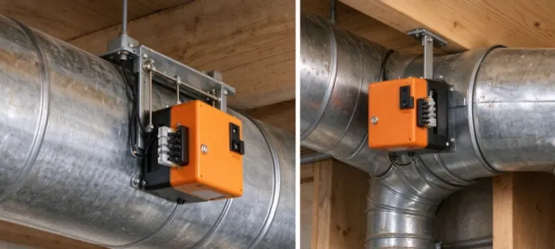
Installation Rules That Decide Performance
Frames, blades and mechanisms must stay reachable.
- Handwheels sit 1.5-1.8 m above floor or platform.
- Keep 200 mm clear around the operating face.
- Never cast a damper into a structural layer.
- Support any damper heavier than 50 kg separately.
- Motorised and CAV dampers get their own hangers.
- Check valve, CAV and fire damper direction.
- Fire damper within 200 mm of a rated wall face.
- CAV body level within 2 per mille.
- CAV needs 1.5 × damper width of straight duct upstream, 0.5 × downstream.
- Oblique-insertion slide dampers face the sliding plate into the airflow, opening upward when horizontal.
- Level tolerance ≤3 per mille; plumb ≤2 per mille.
- Bolt or clip spacing ≤150 mm.
- Clean cleanroom dampers before installation: wipe the interior, seal both ends, and remove plates only after positioning using lint-free material.
Banned gasket materials:
- Foam plastics.
- Thick cardboard.
- Asbestos rope.
- Lead-oil hemp.
- Felt paper.
Butt joints must be stepped or tongued and sealed with sealant. Never paint a gasket.
Commissioning Procedure for Dampers
Pre-Functional Checks
Verify type, size and leakage class against schedule.
- Check actuator model, voltage and wiring.
- Confirm access and label.
- Confirm blade movement by hand.
Electrical checks for motorised units:
- Insulation resistance.
- Earth resistance.
- Dielectric withstand.
- AC and DC operating voltage.
- Static and dynamic power at maximum differential pressure.
- Control and feedback signal test.
Functional Performance Test
- Run a full stroke test from 0° to 90°.
- Test fail-safe by removing power.
- Leak-test airtight units individually.
- Read pressure drop at design flow.
- Verify feedback signal matches position.
Documentation and Handover
- Test records per damper tag.
- O&M manuals with actuator data.
- Damper schedule with final positions.
- Final blade angle, painted on the damper, recorded per tag.
- Commissioning report signed by the agent.
Common Faults, Mistakes and How to Avoid Them
A bigger actuator fixes a stiff damper. Stiffness usually means blade misalignment or a blocked blade.
Per SMACNA HVAC Systems — Testing, Adjusting, and Balancing (TAB) Manual §8.4, increased actuator torque does not compensate for mechanical binding; root cause must be diagnosed and corrected before upsizing.
Fail position can be decided on site. It must be decided in design.
Per NFPA 92 §6.3.4 and ASHRAE Guideline 3.2, fail position is a life-safety design parameter established at the concept stage, not a field decision.
A partly closed blade is silent. Throttling below roughly 30% open regenerates noise and can whistle. Keep modulating dampers above that band where the schedule allows.
Per ASHRAE Handbook — HVAC Applications Chapter 48 (Noise and Vibration Control), blade slot noise rises sharply when open area drops below 30%, due to jet turbulence at the blade gap.
Jason.peng, Deiiang™ product designer, reports that the most repeated site error is ignoring the 200 mm clear space around the operating face. Installers then cannot reach the quadrant or actuator for balancing.
Common faults list:
- Oversized actuator on a small blade.
- Wrong fail position for the smoke strategy.
- Blocked blades from debris.
- No access panel for service.
- Missing fire damper in a rated wall.
- Leakage from a painted gasket.
Maintenance schedule:
- Annual fire and smoke damper test.
- Gasket condition check.
- Actuator stroke test.
- Position mark verification.
Comparison Guide: Choosing the Right Damper for Homes, Commercial and Cleanroom Duty
When choosing a damper type, it is done based on duty conducted and not brand preference. Dampers used in hvac systems in the home are less complicated than cleanroom ones, but the principle remains the same.
The approach to choosing hvac damper types is identified by the three important criteria: duty, leakage and fail position.
Residential USA choices include manual volume, zone, barometric and backdraft types of dampers. Commercial options include control of VAV, fire-smoke and isolation dampers. Cleanroom options include airtight isolation and pressure-relief types.
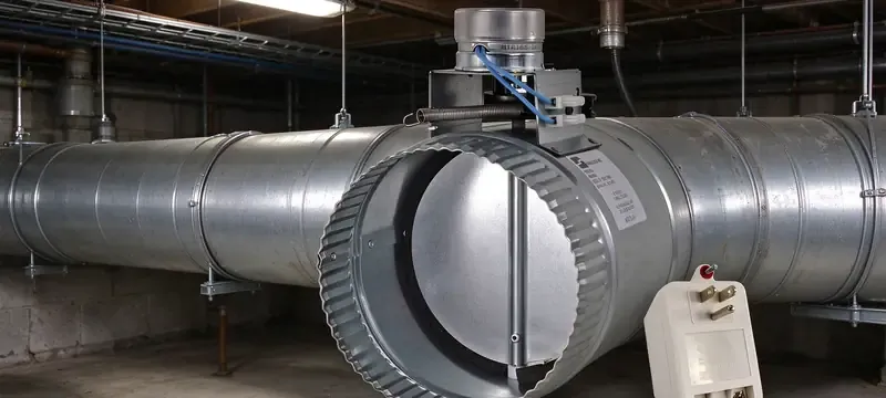
Common Types of Dampers Used in Homes (USA)
Dampers types used for hvac systems in the house typically number four in every house. Common damper types used in houses in the USA include manual volume damper, zone damper, barometric damper and backdraft damper. What other common damper types are used in homes which are not listed here? Occasionally, one may find a motorised zone damper installed in a two-story system.
Residential list:
- Manual volume damper: balances room branches.
- Zone damper: opens or closes a floor or room.
- Barometric damper: relieves excess static pressure.
- Backdraft damper: stops outdoor air backflow.
Commercial and Cleanroom Damper Choices
Financial systems are designed to utilize different types of actuators for HVAC applications, including: VAV control actuators, fire and smoke actuators, and airtight actuators.
Deiiang™ has a matching line of products: Duct Actuators modernized with VAV control actuators, motorized HVAC actuators, and fire and smoke actuators. Other variations include duct actuators accomplished with controllable and gravity actuators.
The cleanroom system includes unique oblique-inserted actuators that are able to address no more than 0.5% high-degree of leakage. The actuators can be supplied by Deiiang™ accordingly to size requirements; however, all types of duct actuators belong to expensive ones and increase project costs accordingly.
Real-Project Case Study and Deiiang Localisation Data
A commercial building with a VAV (ventilation with variable air volume) fresh air supply system was reported to experience airflow deviation of ±25%. The fresh air supply system used a number of boxes connected to the main duct.
This study involves results of measuring the supply airflow rates around the entire building, so it is possible to proceed from the average number of boxes with a given degree of accuracy.
Deiiang™ multi-leaf industrial volume actuators were applied in order to adhere to the requirements of the project. According to the data from the project installed actuators had up to ± 10% deviation from the design values after the installation was done.
The catalog of data indicated that the leakage degree in general was not more than 2%, airtight − less than 0.5%.
Frequently Asked Questions
What are the commonly used dampers in residential buildings?
There are four types of dampers that are regularly used in homes in the United States: manual volume dampers, zone dampers, barometric dampers and backdraft dampers. If it is a two-story home, there may be an additional electrical zone damper installed.
What is the main distinction between controls and volume dampers?
The key difference between volume dampers and control dampers is that volume ones are adjusted manually and keep their settings locked; control dampers, in contrast, adjust automatically. The two types of dampers have a very similar design; however, there is a difference in control signals and actuators.
Which type of dampers is required to stop smoke and fire?
To comply with NFPA 90A and NFPA 92 [5][6][7][8], UL 555 fire dampers and UL 555S smoke dampers and their combinations need to be used. The National Fire Protection Association recommends using the appropriate type of dampers based on barriers and smoke control strategies.
How can I find out the size of the damper pipe?
Make sure that your face velocity is below 20 m/s before calculating pressure drops through a particular damper, while also using the fan budget. You also need to make sure about the leakage classification and actuator torque rating for the surface area of the damper pipe.
Are motorised dampers a better choice than manual ones?
Not necessarily. Manual dampers are less expensive and allow the complete balancing of the system. The choice between the two should depend on the purpose of the system.
How to find the documents about types of damper used in HVAC?
It is recommended to follow the four classes of documents as well as their names. The test standards for air leakage. The test standards for the damper certification. The installation drawings for the dampers.
References
- ASHRAE 62.1 — Ventilation for Acceptable Indoor Air Quality.
- ASHRAE 90.1 — Energy Standard for Buildings.
- SMACNA — HVAC Duct Construction Standards.
- AMCA 500-D — Laboratory Methods for Testing Dampers.
- UL 555 — Fire Dampers.
- UL 555S — Smoke Dampers.
- NFPA 90A — Installation of Air-Conditioning and Ventilating Systems.
- NFPA 92 — Smoke Control Systems.
- EN 1751 — Ventilation for Buildings, Air Terminal Devices.
- EN 15650 — Fire Dampers.
- IMC — International Mechanical Code.
- IBC — International Building Code.
- GB 50243-2016 — Construction Quality Acceptance for Ventilation and Air Conditioning.
- JG/T 14-2010 — Ventilation and Air Conditioning Air Terminals.
- JB/T 7228-94 — Damper Leakage Test Method.