+86 13638632902
 Jason@cleanroomequips.com


 MENU
MENU
These are merely examples of the starting points involved.
The actual final figures will vary depending on the risk assessment performed, pressure-cascade design, classification of the rooms in question and other regulations that need to be adhered to. There is no single standard that applies equally to a pharmaceutical sterile suite and an electronics cleanroom.
A proper risk assessment will outline what the risk of contamination is and what the required pressure direction is as well as when cleaning must occur. These are factors which will ultimately define the airlock door design prior to fixing the final dimensions.
This article outlines airlock design basics in regards to size, pressure and flow. Subsequently, it will describe how to take things such as dimensions and pressure values into consideration, among others. Deiiang™ cleanroom airlock design data is used where catalogue dimensions and model matching are discussed.
Core Functions of Cleanroom Airlock Design
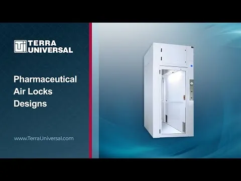
A cleanroom airlock design is intended to protect a process against contamination through the use of pressure cascades, sealing of doors and matching classifications. In terms of personnel and material airlocks, these types of systems serve entirely different and distinct functions.
While personnel airlocks are designed specifically to keep contaminants away from the clean zone, material airlocks are also able to deal with potentially hazardous powders or vapours. Depending on whether the airlock is designed for containment and/or protection, this will dictate how air can be allowed to flow through the system.
An airlock may also need dedicated supply, exhaust, filtration and monitoring. The airlock door design must support those functions without creating a bypass path. The rest of this section covers pressure cascade and door seal performance.
Pressure Cascade Integrity for iso 14644 Classification
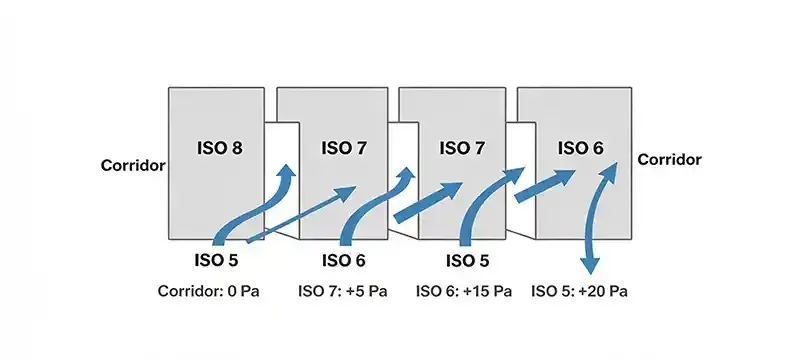
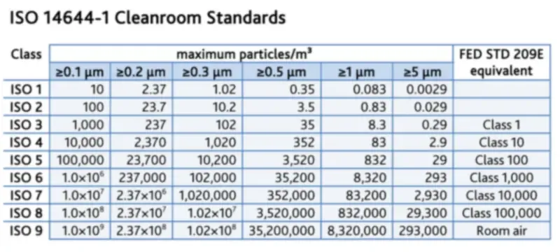
In this environment, pressure cascade integrity means that air is circulating from the clean room to the less clean environment. For example, air passing from an iso class 7 room into the airlock is held at about 15 Pa, while air pressure from the airlock to the corridor of iso class 8 is about 10 Pa.
This figure shows the pressure levels of 15 Pa and 10 Pa represented in the pressure cascade diagram.
It should be noted that iso 14644-1:2015 does not state these pressure levels [1]. The occupancy levels in accordance with ISO 14644-1:2015 are established in Clause 4.2, which describes the typical states of occupancy – as built, at rest, and in operation. The pressure cascade system is separate from classification testing.
If there is an inadequate seal in the airlock entry door, this may produce a loss of somewhere in the order of 5–10 Pa in the air pressure. This might destabilize the cascade and raise the likelihood of the ingress of particles.
The pressure cascade documentation is essential to the airlock design basics. The original reference points and directions for each delta need to be established in the log by the designer.
Airflow Seal Performance Against Particle Ingress
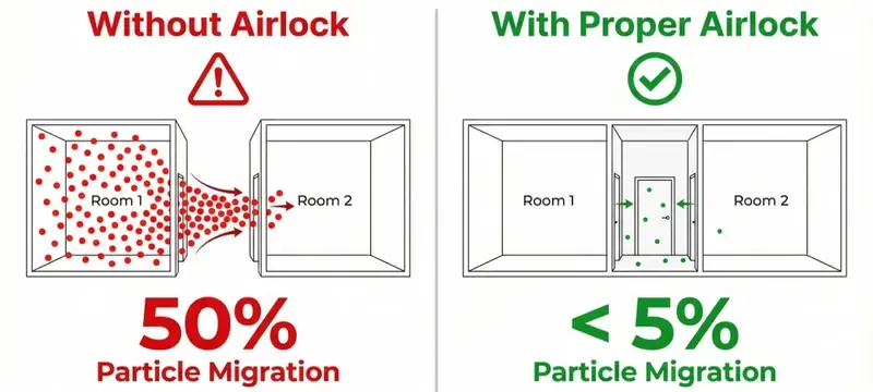
Particles will ingress through the doors where the seals are not compressed sufficiently. The amount of compression can be found with an equation that determines the (original thickness – compressed thickness) / original thickness × 100.
For a gasket that is originally 6 mm thick and now compressed to 4 mm thick, the calculation is (6–4)/6 × 100 = 33%. How much compression is good will depend on the seal manufacturer.
A leakage test can be run at a pressure differential of 50 Pa. Measure the amount of 0.5 µm particles that pass through in a 10-min period. The passing standard is determined by the amount of particles in the air that is significant above baseline levels.
Seal failures usually originate in gaskets that are worn, frames that are out of alignment, or bottom seals that are damaged. The leak path created by each failure will be permanent.
Test conditions should include temperature, humidity, and particle size. The pass criterion should be agreed prior to the commencement of testing.
Standard & Custom Airlock Door Size Specifications
The standard airlock door design has nominal leaf sizes which can be 900 by 2100 mm or 1200 by 2100 mm. The clear opening will be less when taking the frame and seal allowances into consideration.
In the case of a custom clean room interlock door, the size is determined by the footprint of the equipment. Always bear in mind that nominal leaf size and clear opening are two different things.
Table 1: Comparison of Size of Standard and Custom Airlock Doors
| Type | Nominal Leaf Width in mm | Clear Opening Width in mm | Height in mm | Chamber Depth in mm | Comments |
|---|---|---|---|---|---|
| Standard single person | 900 | 850 to 880 | 2100 | 1000 to 1500 | Planning example |
| Standard multiple person | 1200 | 1150 to 1180 | 2100 | 1500 to 2000 | Planning example |
| Wide personnel | 1500 | 1450 to 1480 | 2100 | 2000 to 2500 | Based on the catalogue of Deiiang |
| Equipment pass-through | 1800 to 3000 | 1750 to 2950 | 2100 to 3000 | 2000 to 4000 | Custom interlock door |
| Type | Nominal Width (mm) | Height (mm) |
|---|---|---|
| Standard single person | 900 | 2100 |
| Standard multiple person | 1200 | 2100 |
| Wide personnel | 1500 | 2100 |
| Equipment pass-through | 1800 to 3000 | 2100 to 3000 |
Standard Personnel Airlock Entry Door Dimensions by Occupancy
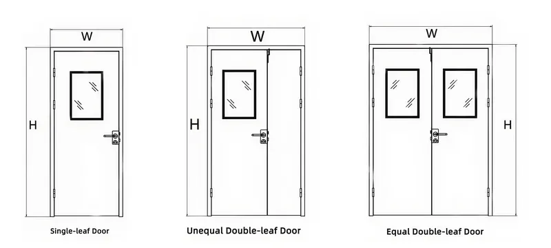
A single-person airlock entry door has a nominal width of 900 mm as a minimum. For multi-person doors, standard widths are either 1200 or 1500 mm. Height is generally 2100 mm.
Specific clearances will depend on door swing, accessibility, personnel carts, and equipment. A planning example may require that there be clearance of 500 mm on the hinge side.
Deiiang catalogue information states that steel clean room doors are available in the following dimensions: 900 × 2100 mm, 1200 × 2100 mm, and 1500 × 2100 mm.
Please check with local authorities regarding local codes to verify that a clear opening of at least 900 mm is required for wheelchair access and check to see if carts require a minimum opening of at least 1200 mm.
Custom Clean Room Interlock Door Sizing for Equipment Pass-Through
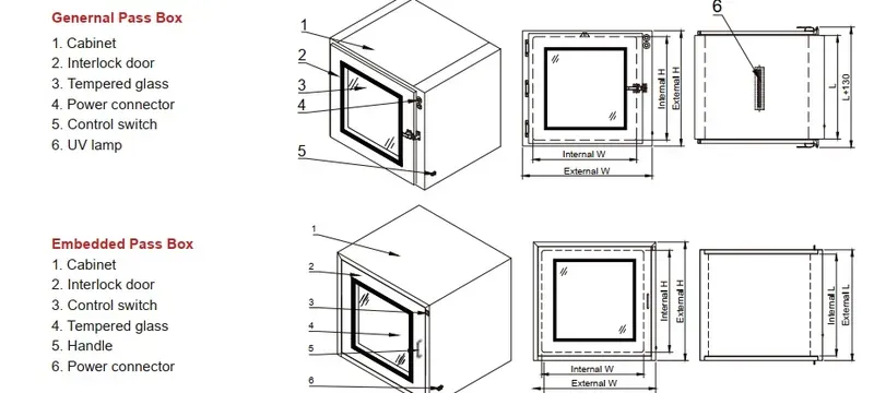
To calculate size requirements for equipment pass-throughs, first calculate the load footprint and then add the handling clearance and turning space and then a safety factor.
Example: 1200 mm width for the load adds 100 mm for each side for a total of 1400 mm for the clear opening. For a load of 1500 mm height, an additional 150 mm must be added for a total height of 1650 mm for the clear opening.
The load carrying capacity of the load is a separately engineered floor capacity, not a door sizing value. A range of 500 to 2000 kg depends on the floor structure rather than the opening.
In the following example, which is fictional, a 2400 mm × 2400 mm custom clean room interlock door is used with an assumed 1800 mm × 2000 mm pallet. The amount of handling clearance varies depending upon the type of forklift or cart used, and the use of 100 mm on both sides is a conservative approach.
Pressure Differential Design Parameters for Airlock Doors

In order for the design of an airlock door to work correctly, it is necessary to set static setpoints, recovery time, and alarm settings. A cleanroom airlock design must have documented reference points for pressure measurements.
ISO 14644 does not set these values, so the design basis for each differential should be written down and kept with the validation records.
Table 2: Pressure Set Point Reference Matrix within the clean room grade
| From zone | To zone | Example setpoint (Pa) | Example alarm band (Pa) | Design basis |
|---|---|---|---|---|
| iso 5 | ISO 6 airlock | 20 | ±5 | Project example |
| ISO 6 | ISO 7 airlock | 15 | ±5 | Project example |
| ISO 7 | iso 8 airlock | 15 | ±5 | Project example |
| ISO 8 | Corridor | 10 | ±5 | Project example |
| From zone | To zone | Setpoint (Pa) |
|---|---|---|
| ISO 5 | ISO 6 airlock | 20 |
| ISO 6 | ISO 7 airlock | 15 |
| ISO 7 | ISO 8 airlock | 15 |
| ISO 8 | Corridor | 10 |
Static Pressure Setpoints for Different cleanroom grades
The example differential for personnel airlock pressure is between 10 and 15 Pa. High grade zones such as ISO 5 may range between 20 and 30 Pa. These are only design examples and do not relate to ISO requirements.
The minimum differential as per iso 14644-3 is not set at all times to 5 Pa [2]. This is the standard from which test methods can be taken. Proper documentation is needed for each setpoint.
The design basis will have to take into account the classification of rooms, process risks, and HVAC capacities. The value for alarm bands may have to vary according to requirements.
Pressure Recovery Time After Airlock Door Cycle
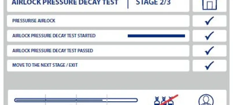
Pressure recovery is defined as the time taken to restore pressure to the required setpoint. A common target is a return to within ±2 Pa in 30 seconds.
In airlocks, pressure recovery depends on leakages in the airlock chambers, exhaust and supply balance, duration for which the door remains open, and response time for the control. Volume flow through air must not be the only factor of recovery.
The pressure differential test techniques outlined in ISO 14644-3 must be applied because validated calculations based on leakage and control response must be applied rather than a simple rule for airflow [2].
The protocol of assessment must allow for the door in the pilot position and a specific tolerance for recovery of pressure. The methods of pressure testing described in ISO 14644-3 provide a good strategy.
Airflow Dynamics Through Airlock System Doors
The dynamics of airflow determine supply distribution, reverse flow blockage, and velocity profiles through the airlock system doors, and must keep the direction of flow stable.
The supply air should generate a uniform curtain at the airlock door. Reverse flow occurs when the pressure drops below the pressure differential cascade setpoint during operation of the airlock door.
Supply Air Distribution & Velocity Profiles in Airlock Chambers
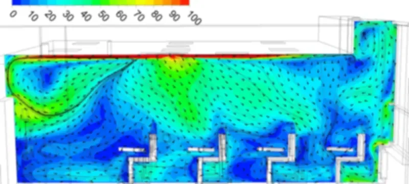
Uniform airflow should be produced with proper positioning of diffusers. A design target of 0.4 m/s at the door plane is common, while the corners should read around 0.2 m/s.
The air change rate in the range of 20 to 60 ACH is only a design target and is not a cited requirement. The places of measurement must cover the air supply face, the door line, and the corners of the airlock.
The velocity should be recorded at the plane of the door in the closed position, and during the cycle. The allowable variance is usually ±20% within the uniformity.
Reverse Flow Prevention During Airlock Door Operation
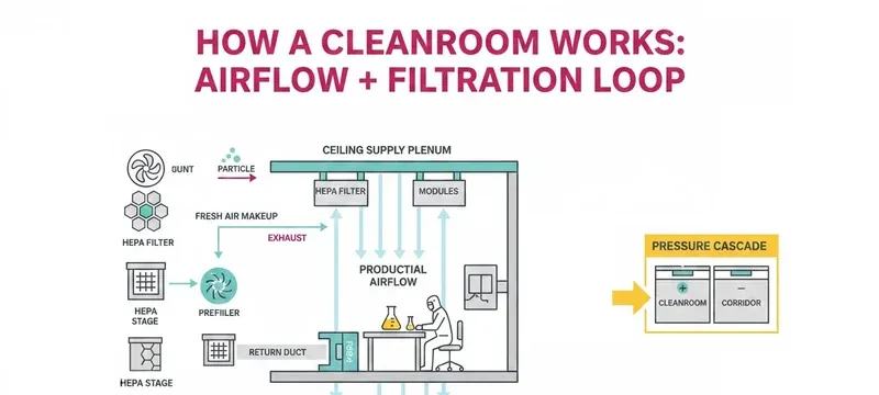
The reverse flow is produced during the opening of the door due to pressure drop, speed mismatch or other external forces such as wind. A design limit of 0.1 m/s reverse flow is sometimes applied.
In the conditions of smoke visualization and airflow measurement, one can verify the direction of airflow during the door cycles. The inner door can be opened only after the outer one has been closed completely.
The adjustment of door speed can reduce the airflow in the reverse direction. Slower opening may decrease the pressure drop but will increase the time of the cycle.
Interlock Control Design for Airlock System Doors
Interlock control does not allow the opening of both airlock system doors at the same time. Normal logic allows releasing one door only when the other one is closed and locked.
The failure mode must be known: power failure, sensor error, fire alarm or emergency exit. Safety override must comply with local life-safety codes.
Electrical Interlock Logic Sequences for Personnel Airlocks
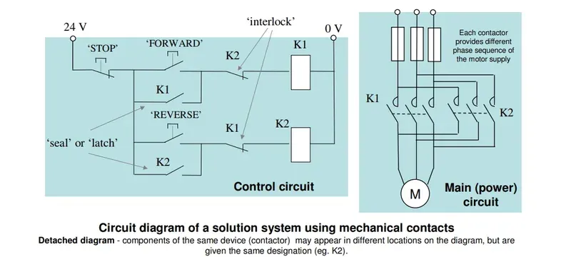
Sequential door release is performed with the help of door position sensors and a door locking timing scheme. The common cycle releases door A and waits until it is closed, and only then releases door B.
To confirm the end of the cycle, one should ensure that both doors are closed during a certain time period. Redundant sensors may be needed according to project specifications but not according to a national code.
The controller should log the door events and alarms, which will help in the validation and troubleshooting process.
Safety Override & Emergency Egress Compliance
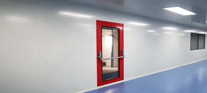
It is necessary to comply with local life-safety conditions for emergency release. The push-to-exit feature should unlock the exit door within the time required by those local requirements.
Activating the alarm system on override status will sound an alert both locally and at a building management system. Inspection periods are determined by local regulations and not by a standard annual period of test.
Testing the override function must be completed during commissioning and any time there is an alteration. Local authority regulations provide the required delay period of release for the alarm.
Construction & Materials for Personal clean room airlock Door
Material is a crucial factor influencing hygiene, durability, and compliance with GMP. Material suitable for a personal clean room airlock door normally includes stainless steel, powder-coated steel, aluminum, or PVC.
Gasket seal options consist of EPDM, silicone, or rubber-plastic strips. A high level of use requires the gasket seals to show resistance to compression set.
Table 3: Material Performance Considerations for Airlock Doors
| Material | Cleanability | Chemical compatibility | Typical finish | Limitations |
|---|---|---|---|---|
| Stainless steel 304 | Excellent | Good for many cleaners | Polished or brushed | Higher price level |
| Powder-coated steel | Good | Average | Spray coating | Finish may chip |
| Aluminum | Good | Good | Anodized or coated | Lower stiffness than steel |
| PVC | Fair | Good for corrosives | Smooth surface | Lower cleanability |
| Material | Cleanability | Limitations |
|---|---|---|
| Stainless steel 304 | Excellent | Higher price level |
| Powder-coated steel | Good | Finish may chip |
| Aluminum | Good | Lower stiffness than steel |
| PVC | Fair | Lower cleanability |
Frame & Panel Material Options for GMP & Industrial Settings
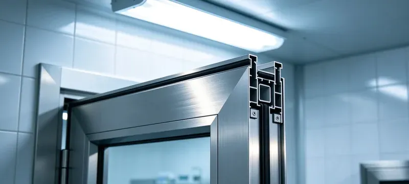
Stainless steel 304 is often selected for pharmaceutical GMP. Powder-coated steel is common in industrial settings. Aluminum is used where a lightweight leaf is preferred.
PVC may work in corrosive environments but has lower cleanability. Deiiang catalogue data lists a 50 mm leaf thickness for painted steel clean doors.
Specific grades or finishes should be identified only when supported by product documentation. Suitability depends on joints, corrosion exposure, and cleaning chemicals, so it should be checked against the facility qualification requirements.
Stainless steel 316 may be needed for aggressive cleaning chemicals. Confirm the finish and weld quality with the supplier before ordering.
Seal System Configurations for Pressure Retention
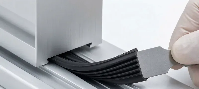
A continuous perimeter gasket design uses a single loop with no joints. Compression set resistance is a key performance property.
Deiiang recommends seal replacement when pressure loss exceeds 10% of the installed baseline. The baseline is measured after installation at the design differential.
A replacement interval of 12–24 months is a Deiiang recommendation. The actual interval depends on cycle count, cleaning chemicals, and measured leakage.
The baseline pressure loss should be recorded after installation. A 10% increase triggers inspection and possible replacement.
Sizing Calculation Methodology for Airlock Design Basics
Airlock design basics for sizing use volume, air change rate, and pressure control. The airflow formula converts chamber volume and ACH into nominal supply airflow.
Pressure control is calculated separately from ACH. Do not add a fixed percentage for door swing, because door swing does not increase chamber volume.
Volume & Air Change Rate Sizing Formula for Airlocks
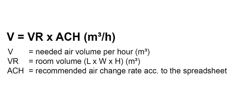
Chamber volume is length × width × height. The required airflow is Q = V × ACH / 3600, where V is in m³, ACH is in h⁻¹, and Q is in m³/s.
Example: V = 3 m³, ACH = 30. Then Q = 3 × 30 / 3600 = 0.025 m³/s, or 90 m³/h. Final size validation checks the door-face velocity.
Pressure loss adjustment factors should be removed unless a documented design method supports them. Calculate pressure control separately from the ACH figure.
The formula assumes well-mixed air. Actual performance depends on diffuser placement and room geometry.
Deiiang Product Model Size Matching for Common Projects
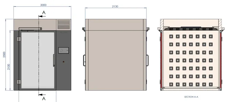
Deiiang catalogue data (Door & Window brochure, pages 2–6) lists standard personnel sizes of 900 × 2100, 1200 × 2100, and 1500 × 2100 mm.
Custom model options for equipment reach 3000 × 3000 mm. Pressure rating and lead time must be confirmed from the current datasheet.
Catalogue values for pressure rating and lead time vary by model. Confirm them on the current Deiiang datasheet before finalising the specification.
Compliance & Validation Standards for Cleanroom Airlock Design
Compliance requires international standards, on-site validation, and documentation. Cleanroom airlock design must align with ISO 14644, EN 1822, and ISO 29463 [1][3][4].
Validation tests include pressure differential, air velocity, particle count, and seal leakage. Periodic re-certification is defined by the facility’s own quality system.
Documentation should include the design basis, test records, and calibration certificates. The facility quality system defines the re-certification interval.
International Standard Alignment for Airlock Door Design
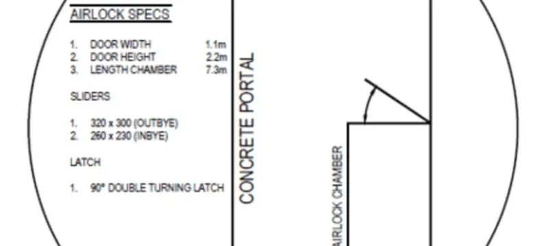
ISO 14644-1 covers classification, and ISO 14644-3 covers test methods [1][2]. EN 1822 references filter performance for HEPA units [3].
ISO 29463 gives containment guidelines [4]. IEST-RP-CC001 provides design practices for cleanroom airlocks [5]. MIL-STD-282 and ASHRAE 52.2 support filter testing [6][7].
On-Site Validation Test Procedures for Installed Airlocks
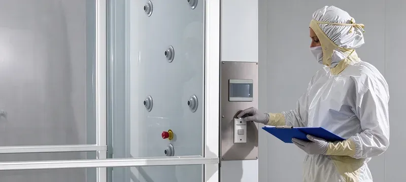
Pressure differential testing uses a calibrated micromanometer. Air velocity and flow measurement uses a thermal anemometer at the door plane.
Particle count verification uses a 0.5 µm particle counter. Seal leakage testing steps include smoke pencil and pressure decay. Pass criteria are defined by the project specification.
Frequently Asked Questions
What is the standard size for a personnel cleanroom airlock door?
A standard single-person airlock entry door is 900 × 2100 mm nominal. Multi-person doors are 1200 × 2100 mm or 1500 × 2100 mm. Chamber depth is typically 1000–1500 mm.
How much pressure differential should an airlock door maintain?
Most applications use 10–15 Pa as a design example, not a universal requirement. Higher-grade zones may use 20–30 Pa. ISO 14644-3 provides test methods, not fixed setpoints [2].
Can I retrofit interlocks to my existing airlock entry door?
Retrofit is feasible for many standard doors with electric strikes and door position sensors. You need an interlock controller, sensors, and locks. Follow local life-safety requirements for egress.
How often should airlock system door seals be replaced?
Deiiang recommends 12–24 months or when pressure loss exceeds 10% of the installed baseline. Visual inspection for cracks and compression set is also required.
Do custom clean room interlock doors meet GMP requirements?
Yes, when material selection, finish, joints, and cleaning chemicals are suitable. GMP also requires documentation and validation. Deiiang custom design can align with GMP when specified.
What is the minimum clearance around a personal clean room airlock door?
A planning example is 500 mm side clearance for maintenance. Front clearance depends on door swing, typically 900 mm for a 900 mm door. Local codes govern the final egress width.
References
- [1] ISO 14644-1:2015, Cleanrooms and associated controlled environments — Classification of air cleanliness by particle concentration.
- [2] iso 14644-3:2019, Cleanrooms and associated controlled environments — Test methods.
- [3] EN 1822-1:2019, High efficiency air filters (EPA, HEPA and ULPA) — Classification, performance testing, marking.
- [4] ISO 29463-1:2017, High-efficiency filters and filter media for removing particles in air — Classification, performance, testing and marking.
- [5] IEST-RP-CC001:2016, HEPA and ULPA Filters.
- [6] MIL-STD-282:1956, Filter units, protective clothing, gas-mask components and related products: performance-test methods.
- [7] ASHRAE 52.2-2017, Method of Testing General Ventilation Air-Cleaning Devices for Removal Efficiency by Particle Size.