+86 13638632902
 Jason@cleanroomequips.com


 MENU
MENU
How do airlock doors work? Airlock doors work by never allowing two doors to open simultaneously. The how do airlock doors work question is exactly what this stage of the design has to settle. The interlocks keep one of the doors closed while it releases the other door so that the pressure differential is absorbed by the interlock chamber in between the two doors. This is the basic principle of operation for airlock doors.
Therefore, eACH airlock door definition in cleanroom applications returns to the first order of airlock door operation: pressure differentials, buffer volume, and interlock logic. The presence of the airlock door leaves only one solution.
The question is how does an airlock door work during transit. During the transit phase, a sensor indicates that the first door is locked before the second one unlocks. Thus, the buffer volume cleanses the air of particulate matter in order to restore the setpoint.
This article discusses the complete principle and design chain. We will examine pressure differentials, interlock logic, seals, airflow, controls, testing, and airlock door selection criteria based primarily on design principles as per manufacturer recommendations.
Jason.peng, Deiiang product designer, has provided catalogue references and field notes. What is an airlock door? A controlled pressure boundary, not just a door.

Core Operating Principle of Airlock Doors
The basic principle of operation for an airlock door is a controlled pressure gradient. In a cleanroom operating at a higher pressure than the surrounding area, air will push outwards whenever a door is opened. The airlock chamber absorbs this transient flow so that the cleanroom does not.
Without a gradient, particles will disperse uncontrollably in both directions. Thus, the chamber that holds the pressure is designed based on a time differential of 2-5 seconds to hold the room at 1.2 m³.
Basic Pressure Differential Operation
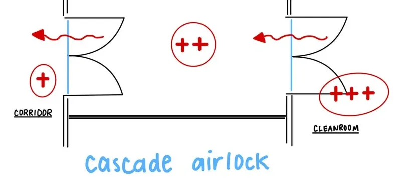
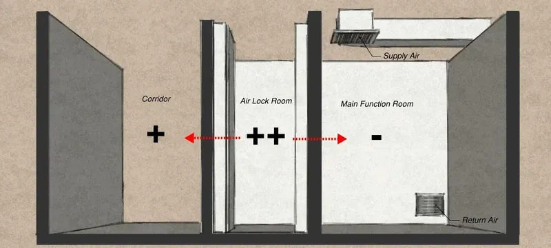
An airlock chamber has a positive (+15 Pa) pressure relative to the ambient area. Hence, the airlock chamber continuously drives air flow through the airlock. The airlock chamber operates at an interstitial pressure of about +10 Pa.
The diagram clearly demonstrates that the air always moves from the higher to lower pressure side. The airlock effectively contains particles that are being carried through the air, in the flow direction.
A pressure difference of 10 Pa is equivalent to roughly a 1 mm water gauge. The important thing here is not the magnitude of the difference, but the air flow direction.
To determine the necessary supply flow, the following equation can be used: Q = A × √(2 × ΔP / ρ). Based on the input data, if the leakage area is 0.5 m² and with 10 Pa drop, Q becomes approximately 30 m³/h.
Sequential Door Interlock Operating Logic
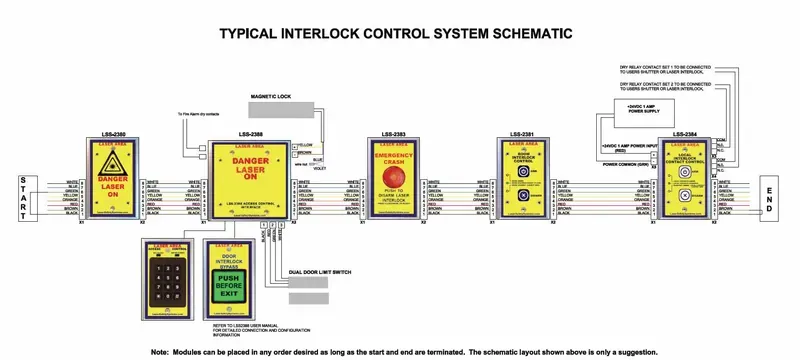
The first rule in airlock operation is the one-door-open rule. Door A must be closed and sealed first, before Door B can be released to unlock. Sensors will confirm the closure of the first door, before enabling the unlocking of the second door.
The process of interlock timing is to put a brief interval of time of 0.5 to 2 seconds between the closing of two doors. When determining the timing for safety, interlock timing supersedes the logic used in every situation.
Interlocking doors must be closed completely before starting the next series of stations. The program records each instance for scheduled maintenance afterwards. A personnel interlock in general will use between forty to sixty cycles an hour.
Rationale for Dual-Door Airlock Design
Why do airlocks have two doors? The reason is simply that the one door would produce a situation in which all of the potential pressure inside the interlock would escape in one small instant. The two leaves reduce the total loss of air volume by half and make it recoverable in a two-step process.
In addition, the space between the two doors acts as an intermediary zone. This buffer zone allows the particles to dissolve before entering the clean area. The volume of the airlock buffer zone of 1.5 m³ can reduce the maximum concentration of particles by 90%.
Table 1: A comparison of a one door airlock design with a two-door airlock design.
| Metric | One door design | Two-door airlock design |
|---|---|---|
| Pressure loss per cycle | 15-30 Pa | 3-5 Pa |
| Number of particles entering | ~10^6 | < 10^3 |
| Recovery time to desired pressure | 2-5 minutes | 20-60 seconds |
| Protection provided to cleanroom | ISO 7-8 | iso 5-8 |
| Metric | One door | Two-door |
|---|---|---|
| Pressure loss per cycle | 15-30 Pa | 3-5 Pa |
| Particles entering | ~10^6 | < 10^3 |
| Recovery time | 2-5 minutes | 20-60 seconds |
| Cleanroom protection | ISO 7-8 | ISO 5-8 |
Contamination Barrier Performance
The total number of particles entering through the two-step isolation of the cleanroom terminates sharply. That is also where what is an airlock door decisions start to differ between facilities. Through a one-door opening, it is possible to admit approximately 10^6 particles of ≥ 0.5 µm. On the other hand, in a dual-door airlock there will be less than 10^3 particles.
Thus the two stages manage to eliminate almost 99% of the contamination entering the cleanroom.
Room Pressure Stability Preservation
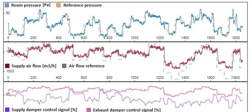
Drop in pressure is the latent cost of each opening. Opening a door with a size of 1200 × 2100 mm will instantly result in a pressure drop of almost 30 Pa·m³/s at 15 Pa.
The difference of only 3-5 Pa in between the two scenarios is enough to make sure that the cleanroom maintains its classification without compromising on it.
Structural Components & Sealing Systems
The performance of the sealing system has a direct influence on pressure holding efficiency of airlock door closing. Even a gap of 0.5 mm may leak significant volumes of air.
Door Panel & Perimeter Seal Assembly
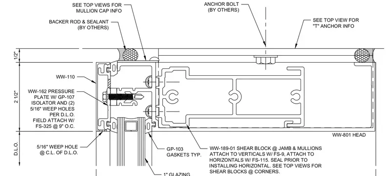
When assembling the door leaf with the sealing of the frame it normally means that the materials used for the leaf have corrosion-resistant properties. For doors made by Deiiang, the painted steel ones carry a thickness of 50 mm.
To achieve an airtight performance, the compression of the seal should be in the range of 30-40% of the height of the gasket. If the seal is compressed properly, the leakage rate will be less than 0.5 m³/h at a pressure difference of 50 Pa.
Frame & Operational Hardware Integration
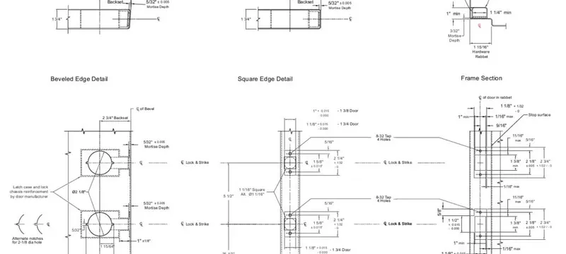
Frames are made of materials that have hinges, latches, and seals at the bottom of the floor. When it comes to frame material, aluminium alloy is widely used, while Deiiang has offered 1.2 mm galvanised steel for a few models of clean door. A frame should have the capability to withstand a lateral load of 200 N.
Hardware should be able to withstand 500,000 cycles. Make use of stainless steel detachable hinges and compression latches to meet the standard. An automatic drop-down sweep seal closes the gap at the bottom when the airlock door is closed.
Pressure Control & Airflow Dynamics
Pressure control helps to maintain the selected set point, both during and after transport as well as in transit, thus allowing the pressure door airlock to modulate the supply and exhaust. Without modulation, the set point will change within a few minutes.
The speed of recovery of the chamber is determined by the air flow dynamics. For example, it takes around three minutes for the volume of 1.2 m³ to recover with 20 air changes per hour.
Differential Pressure Regulation Mechanisms
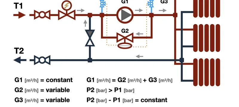
Pressure sensors are taking samples of the chamber every 0.5-2 seconds. With the help of this information, the PID controller is adjusting the variable air volume dampers in order to keep the pressure differential of ±1 Pa. Normally, the set point is maintained at a pressure higher by 10-15 Pa than that in the adjacent corridor.
The three variables that affect setpoint maintenance are the supply flow, exhaust flow, and door state. The controller, when operating a leaf, positions the dampers beforehand, thus decreasing the pressure drop by 40%.
Airflow Pattern Within Airlock Chamber
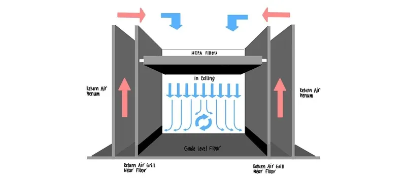
unidirectional airflow makes the particles flow towards the exhaust. Diffusers installed on the ceiling enable 0.3 to 0.5 m/s airflow, making the particles get removed from the clean leaf of the room.
Improper flow pattern sets up dead areas and causes reverse flow of the air inside the chamber. Smoke tests should show no reverse flow of air at the cleanroom's door. Reverse flow indicates entry of contaminating particles in the cleanroom atmosphere.
Common Airlock Door Configuration Types
What are airlock doors if not configurable barriers? We can classify them as openings for personnel and openings for material passage. Each has a specific use case depending on the type of traffic, the size of the opening, and the cycles.
Airlocks vary based on traffic typology, the size of the opening, and the cycle time. Buyers weighing why do airlocks have two doors options meet this trade-off early. Deiiang shows the potential widths of airlock systems which range from 900 × 2100 mm to 1500 × 2100 mm. High-speed roll-up models have a standard width of 1800 × 2400 mm.
Table 2: Comparison of common airlock door configurations.
| Type | Average Size (W × H) | Speed of Operation | Proper Use |
|---|---|---|---|
| Personnel swing | 900 × 2100 mm | 2-4 seconds | ISO 5-8 cleanrooms |
| Material swing | 1500 × 2100 mm | 3-5 seconds | Movement of carts and trolleys |
| Sliding automatic | 1200 × 2100 mm | 1-2 seconds | Cleanliness, limited space |
| Roll-up high-speed | 1800 × 2400 mm | 0.8-1.2 m/s | Logistics and warehousing |
| Type | Average Size (W × H) | Proper Use |
|---|---|---|
| Personnel swing | 900 × 2100 mm | ISO 5-8 cleanrooms |
| Material swing | 1500 × 2100 mm | Carts and trolleys |
| Sliding automatic | 1200 × 2100 mm | Cleanliness, limited space |
| Roll-up high-speed | 1800 × 2400 mm | Logistics and warehousing |
Personnel vs Material Airlock Chamber Designs
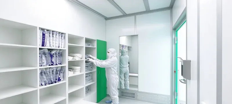
Personnel chambers are simple in style and usually range in width of 900-1200 mm and in depth of 1200-2000 mm. Material chambers are wider, and range in width of 1500-1800 mm to accept carts and pallets.
Traffic volume is another means of distinction between personnel and material airlock chambers. A personnel airlock chamber allows 40-60 entries/hour and a material airlock chamber allows 10-20 pallet moves, with a load capacity of up to 500 kg.
Sliding, Swing & Roll-up Door Variants
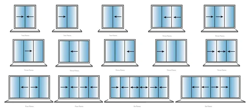
Sliding door systems save space and operate in approximately 1-2 seconds. Swing doors are cheaper but require a clearance of up to 90 degrees, usually more than 1200 mm. Roll-up doors are suitable and effective where rotation speed is key.
Deiiang's fast roll-up door operates at a speed of between 0.8 and 1.2 m/s and features a self-cleaning PVC curtain rated Class 8.2 for fire rating. Track seal technology uses double-row brush seals to prevent insects and dust from entering the chamber.
Interlock & Safety Control Systems
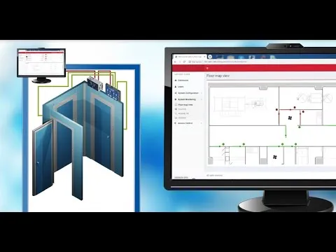
The airlock door lock system is a safety device with logic control. It works by preventing both leaves from being opened simultaneously. Both hardware and firmware act to keep this rule in effect.
Interlocks can be electrical, mechanical, or pneumatic systems. All of them must function as a fail-safe in case of power failure. Safe exit will always be allowed.
Table 3: Interlock categories.
| Interlock Category | Speed of Response | Fail-Safe System | Use |
|---|---|---|---|
| Electrical solenoid | 0.1-0.5 sec | Unlock on power down | Cleanrooms |
| Mechanical cam | 1-2 sec | Blocks one leaf | Low-cost systems |
| Pneumatic | 0.5-1.5 sec | Vents to open | Hazardous areas |
| Interlock Category | Fail-Safe System | Use |
|---|---|---|
| Electrical solenoid | Unlock on power down | Cleanrooms |
| Mechanical cam | Blocks one leaf | Low-cost systems |
| Pneumatic | Vents to open | Hazardous areas |
Electrical & Mechanical Interlock Mechanisms
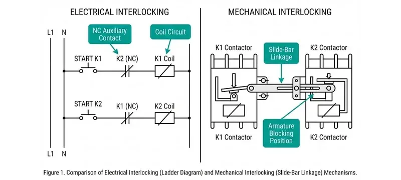
Solenoid locks and position sensors send signals to a control unit. The control unit makes sure that only one of the doors can be opened by software. It scans for inputs every 100 milliseconds on average.
A fail-safe logic unit will release the locking mechanism in case of loss of power. Mechanical interlocks consist of a rotating cam that blocks one leaf. As a rule, the cam has to be operated with a special tool.
Emergency Safety & Override Functions
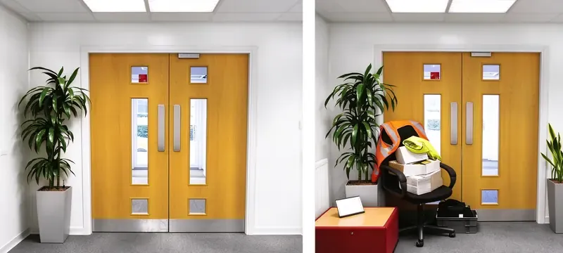
The emergency release system will override the normal interlock operation. The priority of egress should always be kept in mind. Alarm signals sound if both leaves are forced open.
In the power failure mode, both the doors are supposed to automatically unlock after 3 seconds. The battery backup also enables the sensors to continue their operation for 30 minutes.
Installation, Maintenance & Performance Testing
The installation gives the validation of the airlock door as it shows its completeness and gives it the desired significance. The alignment of the frame and compression of seals are very vital in this process. Even a small discrepancy in the alignment by 1 mm may result in a 20% increase in leakage.
Maintenance maintains the leak rate within the limits and Deiiang recommends seal revision every 6 months. The lubrication of the hardware should be done every 3 months.
Field Installation & Sealing Validation
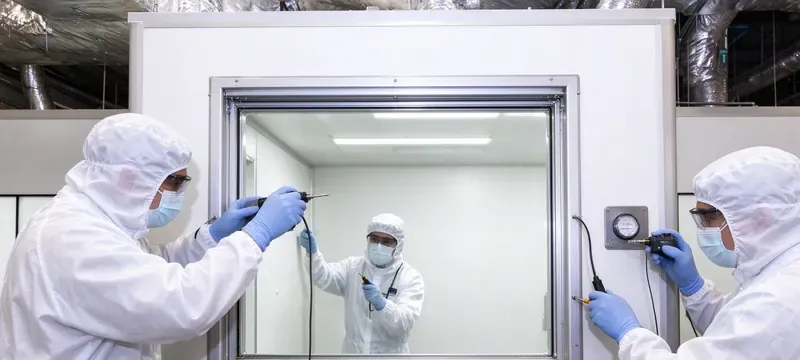
The installation process begins with the alignment of frame to the level of 1 mm in every meter. There should be continuity in the sealing gasket around the complete perimeter. Thereafter, the hinges should be adjusted to ensure uniform compression.
Jason.peng, the product designer from Deiiang, mentions one critical thing that people do while installing hinges. Over-tightening of hinges causes wear and tear at the cushions and may lead to voided warranty. Always use a feeler gauge in order to confirm uniform compression of 30% at all times.
During commissioning, a pressure decay test is administered which states that if a 1.2 m³ chamber holds at least 15 Pa for 60 seconds, it means that it is fine. If there is a failure, then rechecking of the seal at the bottom sweep should be done.
Routine Maintenance & Leak Rate Testing
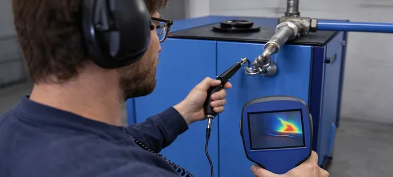
Seal change should be done after every 12 to 24 months and hinge/latch lubrication should take place every 3 months. Engineers comparing what is an airlock door specifications see the same pattern here. The timing of interlock should also be validated every 6 months.
Leak detection takes advantage of an accurate flow measuring device. Deiiang field data cites 0.5 m³/h as leakage under 50 Pa with a sealed door. The above figure is based on project reporting but does not indicate consistency across the board.
Standards Compliance & Product Selection Guidance
Standards compliance is what makes a good design verifiable. iso 14644-1 defines limits for classification, while iso 14644-3 describes the actual methods [1][2].
Selecting the correct airlock relates to its intended use. Deiiang has painted steel airlock, galvanized steel airlock, and stainless steel airlock models available, each of which has different ratings for both pressure and cycles.
International Cleanroom Standards Alignment
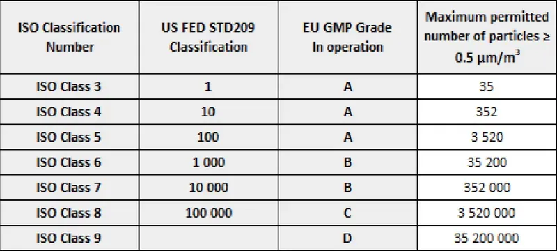
ISO 14644-1 specifies particle limits, while ISO 14644-3 provides procedures for testing [1][2]. EN 1822 indicates degrees of filter efficiency [3], and IEST-RP-CC001 concentrates on HEPA and ULPA filtration [4].
Table 4: Compliance matrix outlining relevant airlock design features.
| Feature | ISO 14644-1 | ISO 14644-3 | EN 1822 | IEST-RP-CC001 |
|---|---|---|---|---|
| Particle classification | Yes | — | — | — |
| Pressure decay testing | — | Yes | — | — |
| Filter efficiency | — | — | Yes | Yes |
| Airflow uniformity | — | Yes | — | — |
| Feature | Applicable standard | Covered |
|---|---|---|
| Particle classification | ISO 14644-1 | Yes |
| Pressure decay testing | ISO 14644-3 | Yes |
| Filter efficiency | EN 1822 / IEST-RP-CC001 | Yes |
| Airflow uniformity | ISO 14644-3 | Yes |
Guidance from ASHRAE provides the basis on which to determine pressure and airflow designs [5]. Collectively, they work together to cover the areas of classification, testing, filtration, and system design.
Deiiang Airlock Door Product Selection Guide
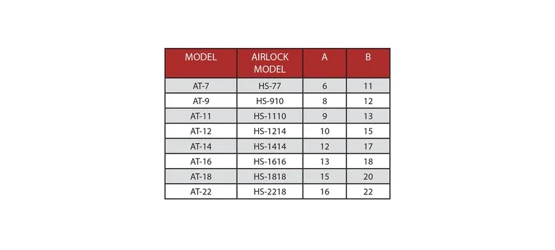
The first consideration is the type of cleanroom. iso class 5 and 6 requires a sealed airlock to have a minimum level of 15 Pa, while iso class 7 and 8 can use 10 Pa and a reduced cycle rate.
Deiiang catalog information: with respect to the painted steel cleanroom door, it features a 50 mm thick leaf. The galvanized steel door comes in sizes of 900 × 2100 mm, 1200 × 2100 mm, and 1500 × 2100 mm. The standard vision size will be 600 × 400 mm and made with double glazing.
Table 5: Selection of Deiiang airlock door models.
| Model | Leaf thickness | Size | Best suited for |
|---|---|---|---|
| Painted steel cleanroom door | 50 mm | Customized | iso class 5-7 cleanroom |
| Galvanized steel cleanroom door | 0.8 mm | 900, 1200, 1500 × 2100 mm | Food, pharmaceuticals, electronics |
| Air operated automatic sliding | 0.8 mm | 1200 and 1500 × 2100 mm | Operating theater |
| Rapid rolling curtain | 0.8 mm PVC | 1800 × 2400 mm | Warehouse and logistics |
| Model | Size | Best suited for |
|---|---|---|
| Painted steel cleanroom door | Customized | ISO Class 5-7 cleanroom |
| Galvanized steel cleanroom door | 900, 1200, 1500 × 2100 mm | Food, pharmaceuticals, electronics |
| Air operated automatic sliding | 1200 and 1500 × 2100 mm | Operating theater |
| Rapid rolling curtain | 1800 × 2400 mm | Warehouse and logistics |
Based on data from Deiiang internal testing conducted in 2025, this performance data is derived from laboratory controlled tests conducted under laboratory conditions. Performance will vary in actual environments.
Frequently Asked Questions
What is an airlock door definition for cleanroom applications?
The definition of airlock should refer to an airtight containment chamber consisting of dual airlock doors allowing for cross-contamination to occur through the use of interconnected doors.
Table 6: Key function versus design constraint for a cleanroom airlock door.
| Key function | Required conditions |
|---|---|
| Pressure separating | 10-15 Pa predetermined value |
| Pollution control | Two-level protection |
| Access to transit | Interlocked doors |
| Airflow pattern | One-way movement |
| Key function | Required conditions |
|---|---|
| Pressure separating | 10-15 Pa predetermined value |
| Pollution control | Two-level protection |
| Access to transit | Interlocked doors |
| Airflow pattern | One-way movement |
Why do airlocks have two doors instead of a single door?
By preventing the free flow of air, two leaves will ensure maximum flow. With only one leaf, the air would quickly regain the pressure differential throughout the entire airlock. An airlock composed of interlocked double leaves will guarantee that all particles are blocked so they cannot enter the clean chamber.
How does an airlock door lock interlock system function?
Airlock door locking mechanism utilizes sensors and controller to implement the one-door rule, using a time delay between 0.5 and 2 seconds. However, it is possible to exit in case of emergencies.
What is a pressure door airlock primarily used for?
A pressure door airlock provides the means for pressure differentials to exist at the boundary. This is done to protect cleanroom class and to isolate operations. Typical users of this device include pharmaceutical companies and manufacturers of electronics and food.
How to ensure reliable long-term airlock door closing performance?
Seals must be inspected every six months. The hardware must be adjusted and the locking mechanism calibrated once a year. Seals will need to be changed every 12-24 months.
The rule of thumb is that if the seal is more than 20% worn out, it must be replaced to prevent the risk of leakages.
What is an airlock between doors in industrial manufacturing facilities?
What is an airlock between doors other than an environmental transitional zone located between two areas where personnel or materials can be decontaminated without stopping production. It provides pressure isolation without stopping production.
References
- [1] iso 14644-1:2015, Cleanrooms and associated controlled environments — Part 1: Classification of air cleanliness by particle concentration.
- [2] iso 14644-3:2019, Cleanrooms and associated controlled environments — Part 3: Test methods.
- [3] EN 1822-1:2019, High efficiency air filters (EPA, HEPA and ULPA) — Part 1: Classification, performance testing, marking.
- [4] IEST-RP-CC001.6, HEPA and ULPA Filters.
- [5] ASHRAE Handbook — HVAC Applications, Chapter 16: Clean Spaces.