+86 13638632902
 Jason@cleanroomequips.com


 MENU
MENU
A cleanroom that is future-proofed ensures that contamination control is always available while at the same time being able to make any necessary changes to accommodate any advancements in production, processes and compliance. By designing with the notion of change in mind, it avoids costly mistakes during production.
For example, in many situations manufacturers have the need for adding automated assembly equipment and the amount of floor space is apparently enough, however, there will be problems with making sure that paths for equipment, power capacity, exhaust processes and service clearances are suitable.
As a result, what could have been a simple upgrade of equipment turns into vast remodeling of layout, the HVAC system and validation.
The true adaptability in place is ACHieved through planning the design of layout, air systems, utilities and change management properly and properly coordinating their work, rather than just using demountable panels for the walls. Future-proofing doesn’t mean you’ll never have to rebuild. It means planning ahead so that when things change, you can adapt with less cost, less downtime, and less risk.
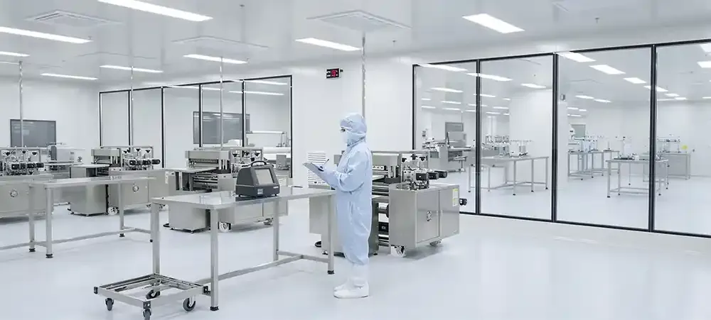
What Makes a Cleanroom Future-Proof?
There are three different ideas related to a long-term approach toward adaptability. People tend to mix the concepts but they can fulfill different needs.
Flexible Design
A flexible cleanroom design makes it possible to meet rearranged process needs, changed equipment, and modified flows while not losing classification efficiency.
Modular Design
Modular construction involves the use of homogenized parts of walls, ceilings, and utility systems. It is possible to improve the speed of the process with modular construction.
Scalable Design
A scalable modular cleanroom can increase its capacity in stages. It requires the presence of space for enlargement, capacity parameters in utility systems and the points for connection.
Common Changes That Outgrow Existing Cleanrooms
Many cleanrooms end up non-usable because there were unforeseen changes in the methods of performing the processes, final results, and quality requirements.
Process & Equipment Changes
- Larger or heavier automated equipment with different vibration limits
- Increased heat, moisture, or process exhaust loads
- New utility demands: compressed air, vacuum, process gases
Capacity & Operational Shifts
- Shift from single-shift to 24/7 operation
- Scale-up from pilot to full volume production
- Bottlenecks in gowning, material transfer, or waste handling
Contamination & Compliance Changes
- Tighter particle or biocontrol requirements
- New contamination sources from process changes
- Updated regulatory, customer, or internal quality standards
Planning Tip: Separate requirements into known needs, anticipated additions, and improbable options. Leave room for potential upgrades without overspending to build everything.
Six Core Principles of Flexible Cleanroom Design
These principles balance initial cost with long-term adaptability across all major cleanroom systems.
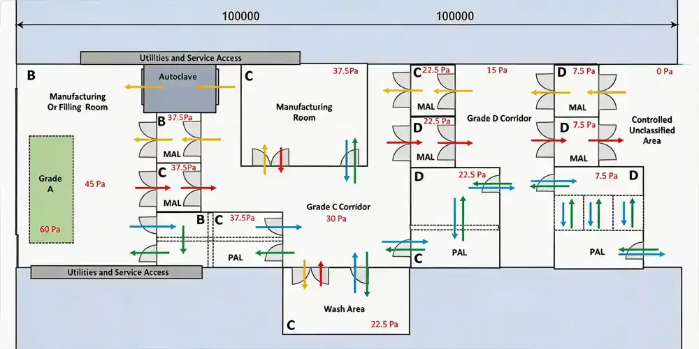
1. Space & Layout Planning
Plan equipment locations considering maintenance and the flow of materials. Ensure there are clear directions for future equipment to enter the workspace.
2. Envelope & Wall Systems
Use standardized demountable wall systems to maintain integrity, cleanability, and chemical resistance.
Aluminum H-tongue profiles with raceway utility channels retain panel integrity during movement. Medical-grade neutral silicone gaskets facilitate clean demounting.
Panel reuse can increase from field-sealed construction (30% reuse) to over 85% with more detailed panels designed for reassembly.
Engineer's Field Note: The False Modularity Trap
Many wall panel suppliers claim 100% reuse. In actual cases, field teams drilling utility penetrations through sandwich panels result in a 70% panel scrap rate for retrofits. Routing utility pillars and having pre-punched module ports will keep the value of the wall panels.
3. HVAC & Airflow Design
Projected system sizes should align with actual process loads, not defined areas. Systems should have zones for capacity that can be expanded in phases.
Review stability and energy efficiency of each successive stage of the project. Avoid oversized fans that will run at very low speeds and create unstable static pressures.
Engineer's Field Note: Oversized Fan Syndrome
Designers will oversize AHU fans “to give enough capacity for expansion” and then run them virtually constantly at low speeds. This results in motor overheating, unstable static pressures, and turbulent airflow. Use modular AHUs or distributed ffus instead of oversized systems.
4. Utility Infrastructure
Make provided services easily accessible, isolatable, and labeled for power, process gases, cooling, and exhaust systems.
5. Monitoring & Control
Prioritize the placement of sensors to ensure proper representation, then optimize the accessibility of services. Accuracy of measurement should not be traded for convenience of calibration.
Engineer's Field Note: PAO Test Port Clearance
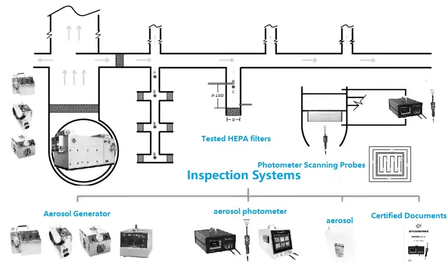
If HEPA housings are mounted tightly to structural beams, there will be no space for upstream PAO aerosol injection probes during validation. Always provide a minimum of ≥150mm clearance above filter banks for access of leak-testing equipment.
6. Documentation & Change Control
Keep records of the as-built design with details such as setpoints and test history. Well-documented changes reduce the potential for risk of future flexibility and expansion of the original design.
Re-validation scope follows iso 14644-2 change classification:
- Minor change (single equipment swap): smoke pattern test + local particle count only
- Major change (wall moves / duct reconfiguration): full airflow, pressure, recovery time, and integrity test
Scalable Modular Cleanroom Expansion
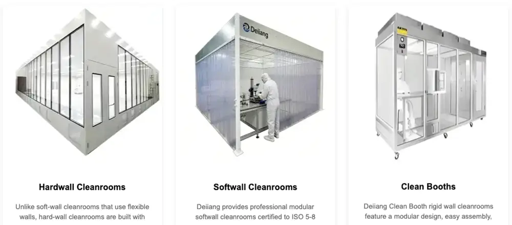
Modular expansion works best when predictable demand occurs, the process units repeat, and the site's infrastructure allows for phased connections.
Preconditions for Successful Expansion
- Structural and fire code compliance for extended footprint
- Sufficient upstream HVAC, power, and utility capacity
- Containment isolation between operating and construction zones
- Defined sequence for connection, commissioning, and release
Managing Pressure Cascades & Cross-Contamination During Live Retrofits
When adding capacity to an operating cleanroom, maintain +10 to +15 Pa positive pressure in the production zone.
Construct a temporary negative pressure airlock buffer between the construction zone and the active zone. To maintain the required –5 to –10 Pa pressure on the construction zone, utilize a dedicated negative air machine.
This stops dust from wall or duct penetrations from entering classified spaces while working.
| Dimension | Modular Approach | Conventional Site-Built |
|---|---|---|
| Layout change | Component reuse with interface limits | Demolition and rework scope |
| Schedule | Prefabrication + site connection | Multi-trade on-site coordination |
| Customization | Standard module limits | Highly customizable |
| Future expansion | Defined connection points | Depends on as-built conditions |
Calculating the ROI of Adaptable Design
When assessing options, consider the full lifecycle cost, rather than initial capital cost.
Lifecycle cost = CAPEX + energy + maintenance + retrofit cost + downtime impact + validation cost.
Let’s look at three options: minimum build only, reserved interfaces, and full spare capacity. Let’s use no growth, planned growth, and unplanned growth scenarios for our example.
Recommended Capacity Reserve Benchmarks
| System | Recommended Reserve | Interface Type | Critical Guidance |
|---|---|---|---|
| AHU airflow / static pressure | 15% – 25% | Blind flange ducts, damper taps | Use VFD fans; avoid oversizing to point of unstable low-speed operation |
| Process exhaust | 30% – 40% cross-section | Pre-installed damper branches | Size corrosive / hazardous exhaust material for final duty from day one |
| Electrical distribution | ~20% spare circuits | Dual busbar, reserved breaker positions | Reserve bus capacity and cabinet space; defer expensive breakers until needed |
Key Rule: Do not use a common spare capacity percentage for all systems. Size reserves based on load type rather than a uniform percentage.
Cleanroom Expansion Reserve Estimator
Let’s see if we can identify potential reserve utility levels and estimate possible downtime reduction for planned growth.
Recommended AHU Static Pressure Reserve: 0%
Recommended Electrical Distribution Reserve: 0%
Estimated Downtime Saved vs. Field Retrofit: 0 hours
Deiiang Case Study: 1,800m² Semiconductor Packaging Cleanroom
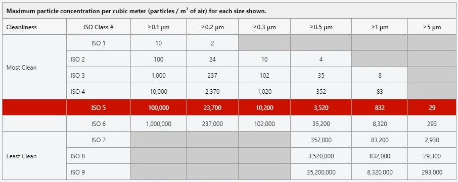
Project: Semiconductor back-end packaging facility in Suzhou, China. Phase 1 consisted of an 800m² ISO Class 7 Assembly Line, while Phase 2 was completed in 18 months, and extended the test area to 1,000m² ISO Class 6.
Challenge
The production line could accommodate a maximum 48-hour shutdown for tie-in. Estimated traditional duct modification and ceiling work would take more than 120 hours.
Deiiang Engineered Solution
We implemented a dual-bus electrical design and a split modular AHU system.The first phase installed 45 FFUs and included prefabricated ceiling slotted blind flanges. Each end of the ducts was equipped with factory-installed bubble-tight isolation dampers.
Result
Phase 2 was completed in less than 36 hours, with the tie-in for an additional 65 FFUs and ductwork. Compared to full field rework, the estimated approach saved 65% of the planned downtime and more than $140,000 in work that would have been lost and reworked.
Common Design Pitfalls to Avoid
These mistakes reduce adaptability and increase retrofit cost and risk.
- Modular walls = adaptability. Also verify HVAC, utilities, and operational compatibility.
- Uniform spare capacity rules. Size reserves per load type, not a blanket percentage.
- Production area only reservation. Also plan gowning, transfer, storage, and waste capacity.
- No retest after layout change. Match testing scope to change impact and risk.
- Sensors moved for calibration ease. Prioritize measurement representativeness, then improve access.
- CAPEX-only comparison. Include downtime, rework, and validation in lifecycle analysis.
Readiness Checklist: Is Your Cleanroom Upgrade-Ready?
Use this checklist to assess current adaptability. Verify items that are not confirmed and mark as applicable.
Process & Space
Documented current and foreseeable process requirements
Clear equipment delivery and installation path
Reserved operation, maintenance, and service space
System Capacity
HVAC current load and spare capacity verified
Power, cooling, and exhaust upstream capacity confirmed
Reserved utility connections with defined specifications
Monitoring & Management
Sensor locations provide representative measurements
Control and data systems support planned expansion
Complete as-built and capacity records available
Operations & Economics
Defined construction isolation and shutdown windows
Lifecycle cost comparison across options
Clear owner for future expansion planning
From Concept to Implementation: Action Roadmap
Follow this five-step process to structure your adaptability project.
- Define requirements & change scenarios. Document current needs, expected changes, and planning boundaries.
- Identify system bottlenecks. Map space, HVAC, utility, monitoring, and operational constraints.
- Compare design options. Evaluate fixed, modular, and hybrid approaches technically and economically.
- Phase the investment. Define current build scope, reserved interfaces, and future trigger points.
- Establish ongoing review. Schedule reassessment at key process or technology change points.
Frequently Asked Questions
FAQ 1
What is a future-proof cleanroom?
A cleanroom which can adapt with low rework, downtime, and risk of revalidation due to process, capacity, and compliance changes that can occur in the future.
FAQ 2
What is the difference between flexible and modular cleanrooms?
Construction that can be adapted is referred to as flexible. One approach to building flexible cleanrooms is with modular construction.
FAQ 3
Can existing cleanrooms be upgraded for better adaptability?
Yes. The level of upgradability is dependent on current design, HVAC, and utilities. This would be evaluated through a gap analysis.
FAQ 4
How much spare capacity should be reserved?
There is no general answer. Reserves should reflect the business’s appetite for risk as well as the anticipated and projected load scenario and partial load performance.
When planning for future changes, upgrade paths are designed based on the need for flexibility, not over engineered.
modular clean rooms allow flexibility only when coupled with adequate HVAC systems as well as utility and control systems.
Validated designs must be evaluated and procedures must be constructed for each change, and convenience must never be substituted for the accuracy of measurement.
Free Engineering Feasibility Review
Upload your current cleanroom CAD or PDF layout. Our engineering team, led by Jason Peng, will deliver a free 3-point expansion bottleneck report within 48 business hours.
Request Adaptability Assessment