+86 13638632902
 Jason@cleanroomequips.com


 MENU
MENU
What is a HEPA Fan? An Engineering Overview on Cleanroom Filtration of Air
The Definition of a HEPA Fan through fan filter units
So what's a HEPA fan has always been said about—it really means to the cleanroom world not the same as the HEPA Fan. The HEPA fan is referred to in a technical sense as a Fan Filter Unit or ffu. The HEPA fan typically refers to a unit consisting of a motorized fan along with a HEPA filter in a single setup. The function of the HEPA fan filter unit is to suck in air, filter it through the HEPA filter and blow downwards through the FFU to provide filtered air into the controlled environment.
The confusion arises due to the fact that the average consumer looking for a "HEPA fan" would be thinking of a small air purifier. However, when a facility engineer searches for the same word, he/she would think of an industrial terminal air supply mechanism used in the ceiling of the cleanroom. This article attempts to present the process of looking at the term HEPA fan from a somewhat engineering standpoint since this is where the technical aspect is.
The HEPA fan, packaged industry-style as the Fan Filter Unit, is practically the building block for air purification in cleanrooms. FFUs are typically included in the ceiling grid of a FFU cleanroom. The purpose of eACH HEPA fan unit is to keep the air in the facility clean, whether this means still holding to iso class 8, for a general-use electronics assembly area, or to iso class 5, for a semiconductor fab.
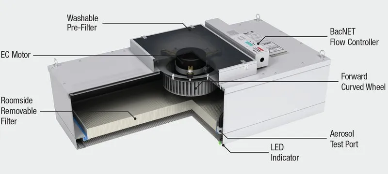
The cutaway view shows how the parts of a HEPA fan fit together: ambient air enters through the washable pre-filter, the EC motor and forward curved wheel push it through the HEPA filter housing, and clean air leaves the outlet face at a uniform velocity.
Figure 1: Cross-section diagram of a HEPA fan filter unit showing the fan intake, motor and blower, HEPA filter housing, and uniform downward airflow discharge.
The core function in this case is simple, but precise. An integrated fan or blower draws in air from the space above the drop ceiling. That air will then pass through the HEPA fan filter assembly, through a HEPA or ULPA filter, and be discharged uniformly from the surface of the unit. Deiiang FFU filters deliver efficiency at a face velocity of 0.45 m/s ± 20%, which is standard in unidirectional flow operations.
The modularity of the cleanroom HEPA fan makes it one of the most appealing options available. As cleanroom standards change, additional HEPA fan units can easily be added or moved around to comply. If a facility has to expand a critical zone, it simply has to put in more FFU modules into the grid where it needs them.
Thus, the HEPA fan filter unit is the preferred choice for terminal filtration, and one of the biggest reasons they are the preferred choice for many industries, including, but not limited to, optoelectronics, aerospace, automotive, biopharmaceutical, food processing, coating, hospitals, and many other industries. After providing FFUs for a large number of cleanroom projects, Deiiang engineers have discovered that the majority of complaints about how the equipment works are not due to the filter but to the specification or sealing or control of the equipment. In this section and the following ones, we have written to help facility teams avoid the repeated issues before they become costly problems.
How HEPA Fans Maintain Cleanroom Integrity
A cleanroom HEPA fan does more than merely move air. It also ensures the integrity of the entire controlled environment. Two factors govern this effect: airflow behavior and particle removal mechanics and both should be understood before specifying or installing any FFU system.
Airflow Behavior: The FFU array behaves by creating a positive pressure plenum above the ceiling of the cleanroom, thus pushing each HEPA fan's filtered airstream into the room below. With the units distributed in an even manner on the ceiling, the airflow will be uniform. In a properly designed system, this will produce unidirectional or laminar airflow in that the air moves in parallel streams downward effectively sweeping particles away rather than allowing them to circulate.
The face velocity of the FFU has a direct relationship to the behavior of the system. If the HEPA fan runs at too low a velocity, the airflow may not be strong enough to ensure that the unidirectional flow is maintained. If it is too high, there will be turbulence created which may actually cause particles to be stirred up rather than removed. This is exactly why Deiiang calibrates the FFUs to be set at 0.45 m/s ±20%.
The HEPA filter contained in the FFU employs three methods for removing particle pollutants: interception, impaction, and diffusion. Interception occurs when a particle follows an airstream through a distance sufficiently close to that of a fiber surface, and thereby comes into contact with the element. Impaction is the process by which particles are affected due to their momentum hitting on to a fiber despite an airstream bypassing it. Diffusion occurs when particles that belong to the sub-micron range process decide to move randomly in space due to Brownian motion which causes diffusion of their particle substance in the environment in which they are placed.
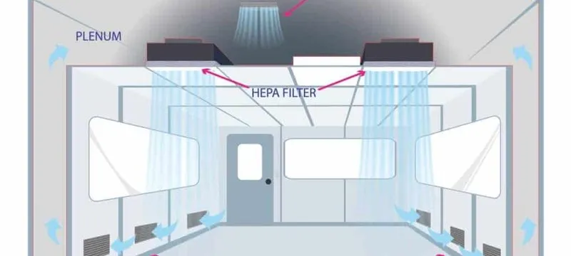
The diagram traces the full loop: supply air enters the plenum, each HEPA fan draws it through the filter ceiling, unidirectional airflow sweeps the workspace, and air returns through low level grilles to repeat the cycle.
Figure 2: Airflow path diagram from the ceiling plenum through the HEPA fan filter unit, into the cleanroom workspace, and returning via the floor or wall returns.
Various mechanisms have an impact on filtering capabilities across various particle sizes. In the case of larger particles, particles are filtered through the interception and impaction filtering mechanisms. At the same time, smaller particles are filtered mainly by the diffusion method the HEPA filter using it for removal particles within the most penetrating size range of particles. Thus, iso classification regulating its performance of the HEPA filters involves even filtering capabilities of the HEPA filter.
Technical Specifications for Engineering Selection
Choosing a cleanroom HEPA fan is an engineering decision. This means that the fan must balance high-efficiency filtration with system resistance, energy consumption, noise, and controllability. Each of these elements works in conjunction with each other; and changing one usually affects the other components.
Establishing Equipment Performance Criteria for the HEPA fan. The most important specification is filtration efficiency. This is based upon the filter grade (H13 or H14 according to EN 1822 certification specifications); but filtration efficiency alone is not enough. The FFU must provide the required rate of airflow despite any resistances created by the filter or by any subsequent air movement.
Airflow is generally expressed as either face velocity or volumetric flow. Because of an FFU's position in providing air into an open cleanroom ceiling, face velocity is the more appropriate measurement. Deiiang ffu units provide face velocity ratings of 0.45 m/sec, ±20%, which creates a specific volumetric flow rate dependent upon the unit size.
The resistance or pressure drop through the filter increases as particulate matter builds up in the filter. As such, the pressure drop across a new HEPA filter typically can be between 200 to 250 Pa, whereas once it is filled with particulates, it may measure between 400 to 600 Pa before it needs replacement. The FFU motor should be capable of providing the required airflow at maximum static pressure, rather than simply at the initial pressure drop condition. If a specified motor fails to conquer the full loaded static pressure drop, it will result in airflow reduction and possible cleanliness problem.
Sound level is very important as well, particularly when building personnel are located near the FFU system. The sound level is usually expressed in decibels measure from a distance of one meter from the FFU. A greater first face velocity will usually lead to a lower sound level, but it will reduce airflow. So this trade-off has to be balanced against cleanliness.
Regulations and Standards. H13 and H14 are the most common grades of HEPA filtration. However, it is often unclear regarding how much a manufacturer must verify the integrity of the seals to ensure operational quality. Our company tests each FFU HEPA filter individually according to the aerosol scanning tests that are superior to the EN 1822 and ISO 29463 minimum requirements on full-face, perimeter, and frame-to-housing interface seals. The rejected filter was not repaired but never as effective as the new one.
This level of quality is important because a filter that passes the spot check may leak for months without detection. After the installation of such a filter in a cleanroom, it is extremely problematic to define its integrity without using additional inspection methods. Using filters which have been scanned before shipment reduces the most common causes of future civil violations.
Types of HEPA fan motors have different efficacy and controllability levels. AC motors have proven to be simple and reliable with respect to their usage, however, they tend to require excessive energy when used at energy-efficient speeds. In contrast, DC motors, specifically electronic commutation (EC), are considerably more efficient across the entire speed range. That is why DC motors are preferred options in establishments that utilize HEPA fan filters nonstop.
Engineering Selection Framework: 4 Important Issues Before You Buy
Before ordering a HEPA fan, engineers should assess four issues that will affect the future costs of a HEPA fan filter unit system. Not dealing with this framework will often result in units that fit the specification but do not perform well.
The four issues are:
Energy Efficiency. The motor of the fan should be compared in terms of power drawn at the functioning stage, and not at rated max. A DC motor, which draws 0.16 amperes constantly, will consume far less power for the year as compared to an AC motor that operates at 118 Watts, even if it has a lower purchase cost.
Consider Noise Levels. Find out how far employees will work from the FFU array and what the acceptable noise level may be. In pharmaceutical packing areas, when noise exceeds 50 dB (A), it may become unacceptable. In a semiconductor manufacturing area, where the ceiling is high, noise levels are much greater and acceptable.
Verify Cleaning and Maintaining Access. Make sure that there is sufficient room in the ceiling plenum and grid to change filters and maintain the fan motor. Because units that are hard to access are serviced less frequently, their failure to be serviced can incur compliance issues.
Compatibility. Check the FFU structure, gasket seal, and seals to ensure compatibility with the ceiling unit. Compatibility should also be checked with disinfectants, fire ratings, and decontamination methods used at the facility.
Comparison Table
Table 1: Basic Engineering Information for Deiiang FFU Series
| Parameter | Series A | Series B |
|---|---|---|
| Filtration Efficiency | H13 (99.97% at 0.3 μm) | H14 (99.995% at 0.3 μm) |
| Nominal Airflow | 1000 | 2500 |
| Face Velocity | 0.45 ± 20% | 0.45 ± 20% |
| Noise | ≤ 52 | ≤ 48 |
| Power Consumption | 118 | 0.16 A |
| Housing Material | Galvanized Steel | Aluminum/stainless steel |
| Parameter | Series A | Series B |
|---|---|---|
| Filtration Efficiency | H13 | H14 |
| Nominal Airflow | 1,000 m³/h | 2,500 m³/h |
| Face Velocity | 0.45 ± 20% m/s | 0.45 ± 20% m/s |
| Noise Level | ≤ 52 dB(A) | ≤ 48 dB(A) |
| Power Consumption | 118 W (AC) | 0.16 A (DC) |
| Housing Material | Galvanized steel | Aluminum/stainless |
Comparison Chart — AC vs DC Energy Consumption Over 12 Months. The chart below is described in text, but can be generated graphically using the template on this page. January through December on the horizontal axis. The vertical axis measures the cumulative energy usage in kWh for one HEPA fan filter unit working 24 hours a day, on the rated operating point.
The AC HEPA fan motor curve (FFU380 at 118 W) rises progressively to about 1,034 kWh in a year. The DC motor curve (FFU470 at 0.16 A on a 220 V supply, 35 W) rises to about 307 kWh during the same duration. The space between the two curves expands each month until month 12, where the DC motor has used about 70% less energy than the AC motor. The visible distinction between both curves is the most convincing rationale for using DC motors in continuous service cleanrooms.
Points to consider when determining the selector motor and control systems
The selection of HEPA fan motor and control systems will add value to the FFU in terms of performance. Instead of outlining all of the specifications, Deiiang presents technical spec cards for motors.
Spec Card – FFU300 AC Motor. Supply: 220 V / 50 Hz; Capacitance: 4 µF; Winding: Copper or aluminum; Bearing: Double-row ball bearing; Insulation: Class E; Certifications: CE, 3C; Dimensions: 123 x 179 mm. Speed: High 1.1 A, 225 W, 770 rpm; Medium 0.92 A, 200 W, 720 rpm; Low 0.76 A, 168 W, 620 rpm.
Spec Card – FFU380 AC Motor. Supply: 220 V / 50 Hz; Capacitance: 6 µF. Insulation: Class B; Dimensions: 123 x 123 mm. There are three operating modes: High (0.57 A, 118 W, 1,070 rpm), Mid (0.52 A, 112 W, 980 rpm), and Low (0.45 A, 98 W, 840 rpm).
The specifications of the FFU400 DC Motor are as follows: The electric current consumed by this motor is 0.16 A ± 8%, and the speed is available in two options (2,000 rpm ± 30 rpm or 930 rpm ± 30 rpm). This device consumes a much lower amount of power in comparison to its AC counter-part.
The FFU470's specifications state that the current consumption is 0.16 A ± 8% and the motor speed is 930 ± 30 rpm. The maximum allowable temperature rise of the winding is ≤ 78K and has CE and 3C certifications.
For projects with multiple HEPA fan filter units, Deiiang provides a group control feature that permits the operation of several FFUs using a single control panel. The line of DC control panels available includes the FFU-3 Network Port Integrated Controller (485 interface power-off memory, PFC – power factor correction max motor power ≤ 180 W) and the FFU-4 Network Port controller (power ≤ 260 W). For maximum flexibility, the dual-port options are applicable.
Manufacturer Insights - Why we Prefer DC Vs. AC Devices. Despite the higher upfront costs, we consistently achieve the energy ROI (Return on Investment) in facilities operating 24/7 in under 18 months. An FFU that operates consistently via a motor powered by AC electricity runs the risk of using more than 1,000 kWh in one year; however, through the use of a similar FFU powered by direct current, using approximately 300 kWh per year would be possible. There may be many FFUs within a manufacturing site so the savings in electricity could easily reach six figures per year. This DC premium is not an indulgence — it's a financial issue.
Case History: Air Flow Optimization in the Pharmaceutical Packing Industry
The following case describes an example of how the right HEPA fan selection plays out in practice. of how an effective HEPA fan filter unit provides the solution.
Case Background of the HEPA fan filter unit retrofit. A pharmaceutical manufacturer set up a new packing line that depended on a stable HEPA fan filter unit ceiling. required to have iso-7 (Class 10,000) cleanliness. The packing area had already been set up in an existing structure featuring limited headroom above the clean area, and the area above the clean room was already filled with mechanical services. The company needed to find a filtration solution that could fit in the available ceiling space but provided the air cleanliness required.
Case Difficulties. The design process had three major issues. First, the headroom of the ceiling was only 600mm — therefore, non-standard height FFUs were not possible. Second, the packing line ran in very close proximity to an office building; therefore, the noise level for the FFU had to be below 50 dB(A) at one meter. Finally, the local regulations (GMP) required that the air flow must be verified, and monitored to make sure that there was separate zone control.
Specific Solution of Deiiang. Engineering teams under the supervision of product designer Jason.peng devised a custom low-profile FFU architecture utilizing DC motors to save space (height) and reduce power consumption. In addition, the DC motors equipped the unit with the FFU-4 Network Port for separate zone control. The regulation system allowed for distinct adjustments of each section, meaning that the essential packaging sector could have more airflow, whilst the adjacent help sector could possess a decreased airflow.
The opening of the FFU structure was completed by using a completely sealed rooftop ceiling structure in order to prevent leaking. F7 filtering sacks were attached behind the FFUs for enfolding large particles and thus increasing the operational period of the HEPA filtering system.
Expert Impression — Computational Fluid Dynamics Modeling in Complex Ceiling Structures. In cases when the client faced the limitations regarding the designated rooftops, the R&D department of Deiiang utilized the application of Computational Fluid Dynamics (CFD) modeling in order to assure that the low-profile design of FFUs will provide laminar air movement through all corners of the ceiling. This service is applicable for all complicated ceiling arrangements, where the simultaneous usage of FFUs, diffusers, and structural beams will create turbulence. CFD modeling allows to quickly resolve possible problems with airflow before the commencement of installation.
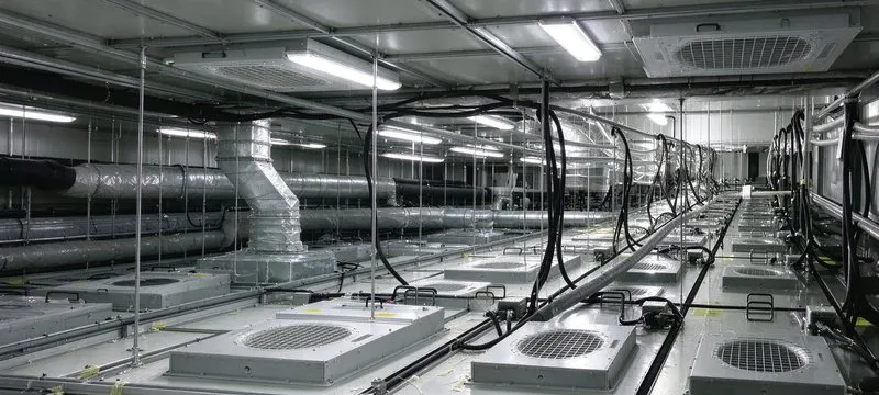
The installed ceiling shows rows of low-profile HEPA fan filter units in position above the packaging line. Each unit can be controlled independently and serviced from the plenum without disturbing the cleanroom below.
Figure 3: Installation photograph of Deiiang FFU structure in the pharmaceutical regulating area, covering the top ceiling and the capacities of Deiiang FFU.
Results and Effect. This building's version demonstrated a 30% drop in energy expenses as compared to the conventional AC motor FFU setup. Post-installation monitoring of the HEPA fan filter unit groups showed that the airborne particles met all iso 7 standards. The noise output was less than 48 dB(A) measured outside of the window on a one-meter distance improving comfort levels of personnel and allowing conducting conversations at the said working site. The regulation system enabled this organization to alter the airflow according to production plans complying with the requirements. The project showed that selecting a HEPA fan for a cleanroom based on thorough engineering design rather than the default option in a catalog will ensure compliance, as well as save operating costs.
Best Practices for Installation and Maintenance
Even if the right HEPA fan is selected, improper installation will not allow the unit to meet its specifications. Installation quality directly influences whether the cleanroom complies with the required ISO classification.
Successful cleanroom HEPA fan installation. It is necessary that each fan filter unit is installed within a ceiling grid system that is continuously sealed. If there are gaps between the FFU housing and the ceiling, then there is a possibility that ineffective air is entering the cleanroom. This is often the reason for failure during cleanroom certification.
The grid in this case must also be constructed so that it supports the weight of the FFU. Depending on the size of the unit, it may weigh between 20 kg to 40 kg, especially comparing models that are different. The design of the ceiling structure must be suitable for suspension so that support is available especially in seismic areas of installation.
Compatibility of the FFU with the ceiling of the cleanroom not only depends on the dimensions. Fire ratings, chemical resistance of the ceiling, and cleanability must also be ensured. In some cases, such as pharmaceuticals centers, both the ceiling grid and housing of the FFU must be constructed of materials with sufficient resistance against hydrogen peroxide use for disinfection.
Checking HEPA Fan Operational Efficiency. One of the most reliable methods of determining when to replace the filter in the FFU is monitoring the change in pressure across the filter. Once the pressure drop reaches the manufacturer-specified final resistance of the HEPA filter, which falls in the range of 400 to 600 Pa, it is time for replacement.
By relying on time-based maintenance schedule, one has to face elimination of the possibility of the pre-filter becoming loaded. In a cleanroom where such maintenance takes place under clean conditions, the HEPA filter will take years to reach final resistance. In contrast, the dustier cleanroom will result in a change within months. Inspection of the pressure drop, therefore, allows for a more accurate determination of the optimal time for replacement based on the conditions rather than following an arbitrary timeline.
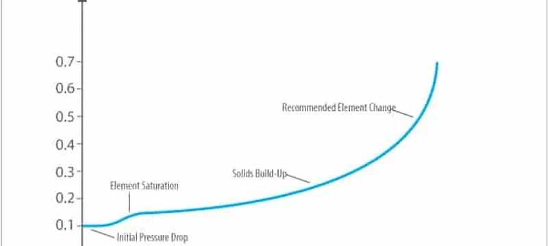
The curve shows how the resistance of a loaded HEPA filter climbs with time. Baseline readings at commissioning let a facility team predict replacement from measured pressure drop instead of calendar dates.
Figure 4: Pressure drop versus time curve illustrating the need for filter replacement of a HEPA filter, showing initial resistance, gradual loading, and the recommended replacement point.
The recommended practice is to obtain baseline pressure measurements when the cleanroom is commissioned and monitor it on a weekly or monthly basis. A sudden drop in pressure drop may indicate breach of filter media or seal, while a gradual increase is indicative of standard loading that is occurring within the cleanroom.
Major Mistakes in Filter Replacement Process
There are three areas in which difficulties with the FFU are most predominant. Each of these difficulties can be avoided simply through proper engineering review and application as to standard procedures followed during installation of the FFU.
Underestimating static pressure of loaded pre-filters of course would be the first occurrence. Although the initial static pressure of the F7 in the clean position is only 60 Pa, the loaded filter will experience a dramatic increase of up to 200 Pa, or more in practice. The same types of static loading that can build up as a result of this type of mistake will cause other variables to be decreased after installation.
Deiiang Professional Tip: Be sure to always to size the FFU motor to the total resistance of the fully loaded pre-filter along with the HEPA filter completely filled to its capacity with a minimum of 10% more capacity designed in. This ensures you never experience underperformance in the life of the installation.
Second on the list of pitfalls of proper FFU application is improperly sealing the grid. Even the tiniest opening at the perimeter of the FFU can create an avenue of particulate free air. As a result, the particle count may exceed the acceptable limit even though the filter passed its scan.
Deiiang Professional Tip: Request either a gasketed or gel sealed interface between the FFU and the ceilings grid; however, be certain to verify the seal during commissioning with a smoke pencil or some aerosol challenge along the perimeter.
Third on the list of pitfalls is failing to perform periodic in-situ integrity testing. It is possible for filters to sustain damage during the installation process that will not be visible to the naked eye, even if the filter passed its factory scan.
Deiiang Professional Tip: Always schedule in-situ integrity testing for not just installation, but at least once per year thereafter. Furthermore, for critical applications Deiiang offers FFU models which have been built with integrated test ports to allow for testing from the ceiling without having to remove the unit from service.
Manufacturer Insights — Rethinking Filter Replacement
Myth of maintenance: it is common for a majority of fan filter unit operators to operate under the assumption that replacing HEPA filters is based upon set time intervals. The practice of time-based filters replacement has two drawbacks. The first drawback involves wasting money by discarding filters when they still have the capacity; the second drawback is servicing filters past the point of its safe operating range. One way to fix these problems is by using differential press sensors to trigger filter replacement based on the actual condition of the filters.
Facilities that make the switch from calendar-based to condition-based filtration usually see savings in the neighborhood of 20% yearly on filter costs because the filters are only changed when necessary. The cost of instrumentation is minimal compared to savings from using data to trigger filter replacement, but the instrumentation can also serve in detecting upstream failures or unexpected particle generation.
Conclusion and Technical Consultation
The selection of the proper HEPA fan for use in clean rooms requires more than specifications. It is necessary to know the application to be used in determining the proper fan filter unit so that there is a match between the cleanliness required, the physical limitations of the installation, and the desired operating costs.
Selecting a HEPA fan filter unit for use in a pharmaceutical packaging line will be different from selecting one for a semiconductor fabrication facility in that the fabrication facility may require ULPA filtration capability and materials that do not outgas. The pharmaceutical operation may require low noise levels, ease of maintenance, and compatibility with decontamination chemicals while a hospital operation may govern the inclusion of self-testing DOP test ports for performing in-situ testing of filter integrity.
Deiiang engineers can help facility teams model the airflow, size every cleanroom HEPA fan, and select the grade of filter and motor type to be used as well as help the team design the control system that will meet the needs of the facility in which they will be installed. Whether it is a single-use FFU service for a small clean booth or a multiple-zone application for a large manufacturing facility, the same level of engineering expertise applies to both applications.
Please contact our engineering office for fan filter unit consultation relative to specific cleanroom air purification applications and to request a Deiiang product catalog, including airflow modeling, CFD analysis for complex ceilings, energy consumption analysis, and project-specific product recommendations.
References
- iso 14644-1:2015 — Cleanrooms and associated controlled environments — Part 1: Classification of air cleanliness by particle concentration. https://www.iso.org/standard/53394.html
- iso 14644-3:2019 — Cleanrooms and associated controlled environments — Part 3: Test methods. https://www.iso.org/standard/75058.html
- EN 1822-1:2019 — High efficiency air filters (EPA, HEPA and ULPA) — Part 1: Classification, performance testing, marking. https://webstore.ansi.org/standards/din/dinen18222019
- ISO 29463-1:2024 — High efficiency filters and filter media for removing particles in air — Part 1: Classification, performance, testing and marking. https://isrsm.gov.mk/en/project/show/iso:proj:84367
- IEST-RP-CC002 — Unidirectional Flow Clean-Air Devices. Institute of Environmental Sciences and Technology. https://www.iest.org/Standards-RPs/Recommended-Practices/IEST-RP-CC002
- ASHRAE Standard 52.2 — Method of Testing General Ventilation Air-Cleaning Devices for Removal Efficiency by Particle Size. https://www.ashrae.org/technical-resources/bookstore/standard-52-2
- EU GMP Annex 1 — Manufacture of Sterile Medicinal Products. European Commission. https://health.ec.europa.eu/latest-updates/revision-annex-1-manufacture-sterile-medicinal-products-2022-08-25_en
Frequently Asked Questions
What is a HEPA fan?
A HEPA fan is an air-filtration device that combines a fan or blower with a high-efficiency particulate air filter. The fan moves air through the HEPA filter, which captures fine airborne particles before supplying or recirculating cleaner air.
How does a HEPA fan work?
The fan creates enough pressure to force air through the filter media. Particles are captured through interception, impaction, and diffusion. Performance depends on filter efficiency, airflow rate, pressure drop, sealing, and installation quality.
What is the difference between a HEPA fan and a fan filter unit?
"HEPA fan" is a general term for a fan-and-filter assembly. A fan filter unit, or FFU, is typically a self-contained ceiling module with a fan, HEPA or ULPA filter, housing, and controls designed for cleanrooms and controlled environments.
What filtration efficiency does a HEPA fan provide?
The efficiency depends on the installed filter and applicable test standard. A common HEPA rating is at least 99.97% removal at 0.3 micrometers, while standards such as EN 1822 and ISO 29463 classify filters using their most penetrating particle size.
Where are HEPA fans commonly used?
HEPA fans are used in cleanrooms, laboratories, pharmaceutical production, semiconductor facilities, hospitals, food-processing areas, and other environments requiring controlled airborne-particle concentrations.
How should a HEPA fan be sized?
Sizing should consider room volume, required air-change rate, target cleanliness classification, process-generated particles, system resistance, filter pressure drop, airflow uniformity, noise limits, and available installation space.
How often should a HEPA filter be replaced?
Replacement should be based on measured pressure drop, airflow reduction, integrity-test results, contamination risk, and the facility's maintenance procedures—not on time alone. Regular monitoring helps determine the appropriate service interval.
Can a HEPA fan remove gases, odors, or all microorganisms?
A HEPA filter captures particles but does not effectively remove most gases or vapors. Activated carbon or other media may be required for odors and chemicals. HEPA filtration can capture many particle-associated microorganisms, but it does not replace validated disinfection or sterilization.